EasyManua.ls Logo

IFR COM-120C User Manual

IFR COM-120C
326 pages
To Next Page IconTo Next Page
To Previous Page IconTo Previous Page
Page #136 background image
4-63
SECTION 4
OPERATION
4-6 INDEPENDENT AUDIO/DATA/SIGNALING GENERATORS
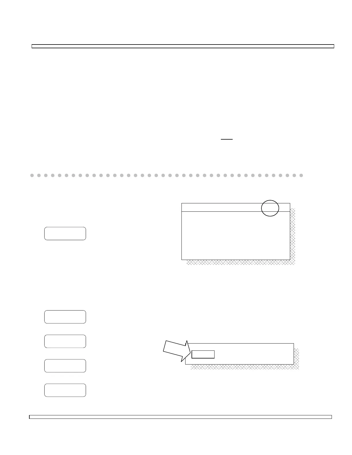
Press the AUDIO GEN INSTRUMENTS Key to access the Audio/Data/Signaling
Generators Operation Screen. The Independent Audio/Data/ Signaling Generators
provide baseband signal generators that are independent of other Operation Modes.
The Audio/Data/Signaling Generators Operation Screen is composed of four sections.
Each section of the screen represents a different generator. The generators are
addressed separately in this documentation. Restrictions that apply to the generators
are primarily related to the output level.
The sum of the generators output level should not exceed 2.5 volts in X1 mode and
25 mV in /10 (divide by 10) mode. If /10 mode is selected, ALL
signal generators are
affected.
The intention is to provide sufficient information to allow the operator to effectively use
the COM-120C to perform specific operator defined tests.
4-6-1 AUDIO GENERATOR-1 OPERATION
Configure and operate Audio Generator-1
as follows:
GEN1
Toggles Audio Generator-1 ON and OFF.
o Cursor to Format and select from the
menu.
o If TONE is selected as Format:
Enter Audio Tone Frequency. Range is 5.0 to 20000 Hz.
Select Shape of Wave as follows:
SINE
Selects Sine wave.
RAMP
Selects Ramp wave.
TRIANGLE
Selects Triangle wave.
SQUARE
Selects Square wave.
1000.0 Hz
SINE
TONE
CONTMode :
Level :
Shape :
Freq :
Format :
AUDIO GEN - 1 ON
0.00 Vp .000 Vrms
1000.0 Hz
SINEShape :
Freq :

Table of Contents

Question and Answer IconNeed help?

Do you have a question about the IFR COM-120C and is the answer not in the manual?

IFR COM-120C Specifications

General IconGeneral
Resolution1 Hz
RF Input Impedance50 Ω
Third Order Intercept (TOI)+10 dBm
Display TypeLCD
Display Resolution640 x 480 pixels
RF Input Protection1 W
Power Requirements100-240 VAC, 50-60 Hz
Input VSWR1.5:1
Phase Noise-80 dBc/Hz @ 10 kHz offset

Summary

COM-120C Communications Service Monitor Operation Manual

Preface

Provides an overview of the manual's organization, scope, and intended audience.

Section 1: Introduction

Introduces the COM-120C, its functions, and basic operation modes.

Section 2: Installation

Provides information on preparing the COM-120C for use and operating precautions.

Section 3: Composite Controls

Details front and rear panel controls, screens, soft function keys, and menus for system interaction.

Section 4: Operation Procedures

Covers configuring and performing various operational tests like RF Generate, Receive, and Duplex modes.

Section 5: Common Practices

Offers suggestions for equipment and screen setups for common RF Generate and Receive practices.

Section 6: Options and Features

Describes optional features and accessories for the COM-120C, including testing capabilities.

Safety and Precautions

General Safety Warnings

Covers high voltage equipment hazards, servicing, case removal, and safety identification terms.

Battery Handling and ESD Precautions

Provides warnings for sealed lead-acid battery use and precautions for handling ESD-sensitive parts.

Appendix A: User I/O Connectors and Pin-Outs

Table of I/O Connectors

Details the connector names, types, signal direction, and signal types for COM-120C I/O ports.

Connector Pin-Out Tables

Provides specific pin assignments for MIC/ACC, GPIB, and RS-232 connectors.

Appendix B - Abbreviations

Soft Function Key Descriptions

An alphabetical reference for COM-120C soft function keys and their descriptions.

Appendix C - Repacking for Shipping

Shipping and Repacking Procedures

Details authorization, tagging, container requirements, freight costs, and step-by-step repacking instructions.

Index

Index-1

Alphabetical listing of topics and their corresponding page numbers for easy reference.