EasyManua.ls Logo

IFR COM-120C User Manual

IFR COM-120C
326 pages
To Next Page IconTo Next Page
To Previous Page IconTo Previous Page
Page #93 background image
4-20
SECTION 4
OPERATION
4-1-5 OSCILLOSCOPE OPERATION SCREEN
The RF Generator Oscilloscope is usable as an abbreviated or full screen
Oscilloscope.
The abbreviated Oscilloscope is visible from the RF Generate Operation Screen and
the SINAD, Distortion and Audio Frequency Level Meters.
The zoomed, or full screen, Oscilloscope maintains the configuration of the
abbreviated Oscilloscope and vice versa.
Oscilloscope parameters set on any of the Operation Screens remain constant on all
screens.
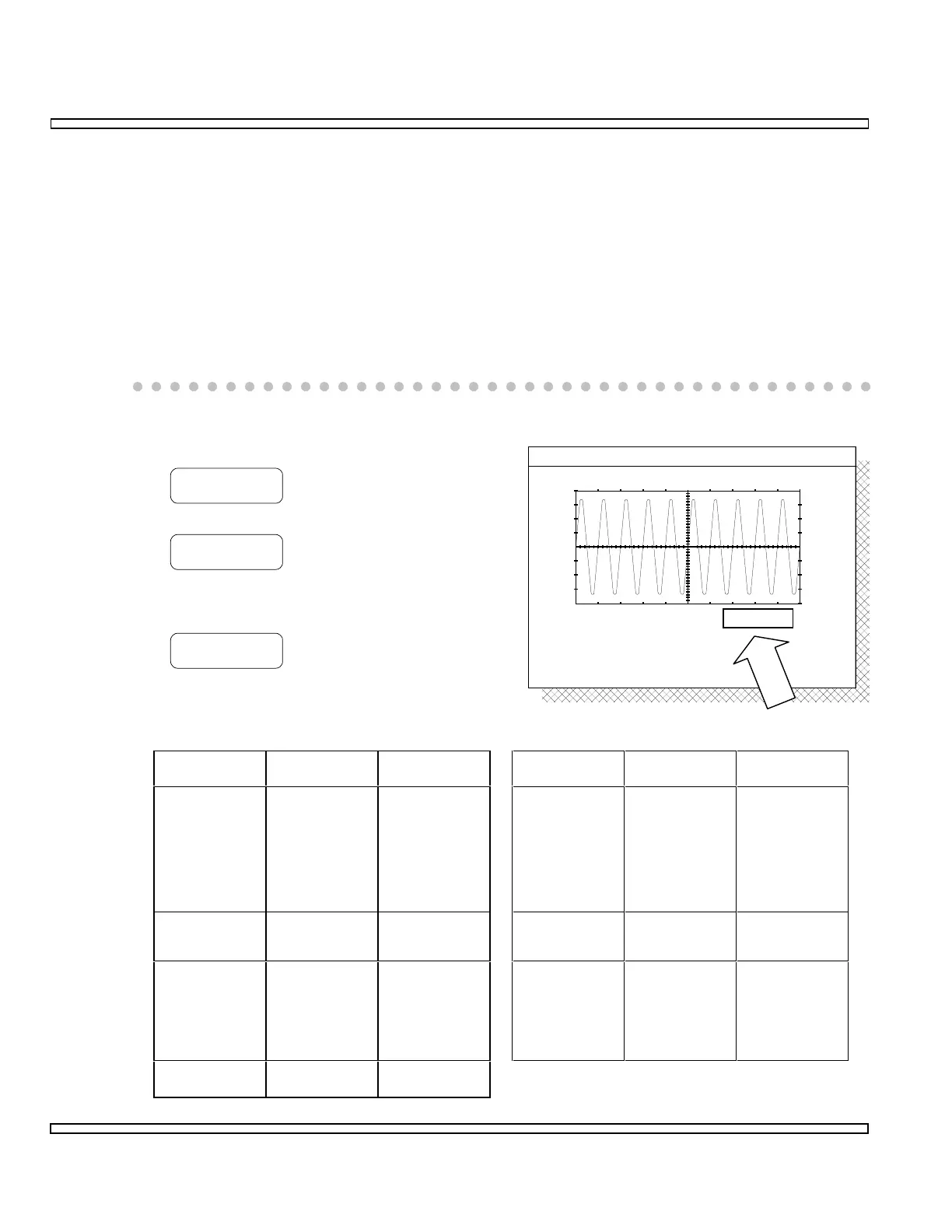
Configuring the abbreviated Oscilloscope is as
follows:
MENU
Accesses a list of sweep settings.
ROLL
To view the scope trace in a roll mode. The
selected sweep rate must be 100 ms/div or
higher.
SLOW
To return to normal mode of operation.
o Select Scope Source. Refer to this selection table.
Source Signal
Input
Signal
Type
Source Signal
Input
Signal
Type
Scope/DVM-
GND
SCOPE/ DVM
Connector
External GND-
Coupled
Signal
Notch
Residual
Internal
Filtered Signal
Notch Filtered
Signal passed
to SINAD and
Distortion
Meters.
Reading is
relative with
no units
applied.
Scope/DVM-
AC
SCOPE/DVM
Connector
External AC-
Coupled
Signal
Audio/Data In AUDIO/DATA
IN Connector
External Audio
or Data Signal
Scope/DVM-
DC
SCOPE/DVM
Connector
External DC-
Coupled
Signal
Int Mod Internal
Modulation
Composite
Modulation
Signal
generated by
Internal
Audio/Data
Generators
Ext Mod EXT MOD IN
Connector
External
Modulation
GENERATE
1 ms/div
SCOPE
1 kHz
SOURCE: Int Mod

Table of Contents

Question and Answer IconNeed help?

Do you have a question about the IFR COM-120C and is the answer not in the manual?

IFR COM-120C Specifications

General IconGeneral
Resolution1 Hz
RF Input Impedance50 Ω
Third Order Intercept (TOI)+10 dBm
Display TypeLCD
Display Resolution640 x 480 pixels
RF Input Protection1 W
Power Requirements100-240 VAC, 50-60 Hz
Input VSWR1.5:1
Phase Noise-80 dBc/Hz @ 10 kHz offset

Summary

COM-120C Communications Service Monitor Operation Manual

Preface

Provides an overview of the manual's organization, scope, and intended audience.

Section 1: Introduction

Introduces the COM-120C, its functions, and basic operation modes.

Section 2: Installation

Provides information on preparing the COM-120C for use and operating precautions.

Section 3: Composite Controls

Details front and rear panel controls, screens, soft function keys, and menus for system interaction.

Section 4: Operation Procedures

Covers configuring and performing various operational tests like RF Generate, Receive, and Duplex modes.

Section 5: Common Practices

Offers suggestions for equipment and screen setups for common RF Generate and Receive practices.

Section 6: Options and Features

Describes optional features and accessories for the COM-120C, including testing capabilities.

Safety and Precautions

General Safety Warnings

Covers high voltage equipment hazards, servicing, case removal, and safety identification terms.

Battery Handling and ESD Precautions

Provides warnings for sealed lead-acid battery use and precautions for handling ESD-sensitive parts.

Appendix A: User I/O Connectors and Pin-Outs

Table of I/O Connectors

Details the connector names, types, signal direction, and signal types for COM-120C I/O ports.

Connector Pin-Out Tables

Provides specific pin assignments for MIC/ACC, GPIB, and RS-232 connectors.

Appendix B - Abbreviations

Soft Function Key Descriptions

An alphabetical reference for COM-120C soft function keys and their descriptions.

Appendix C - Repacking for Shipping

Shipping and Repacking Procedures

Details authorization, tagging, container requirements, freight costs, and step-by-step repacking instructions.

Index

Index-1

Alphabetical listing of topics and their corresponding page numbers for easy reference.