EasyManua.ls Logo

IFR COM-120C User Manual

IFR COM-120C
326 pages
To Next Page IconTo Next Page
To Previous Page IconTo Previous Page
Page #239 background image
6-64
SECTION 6
OPTIONS
6-13-12 MOBILE INIT TEST
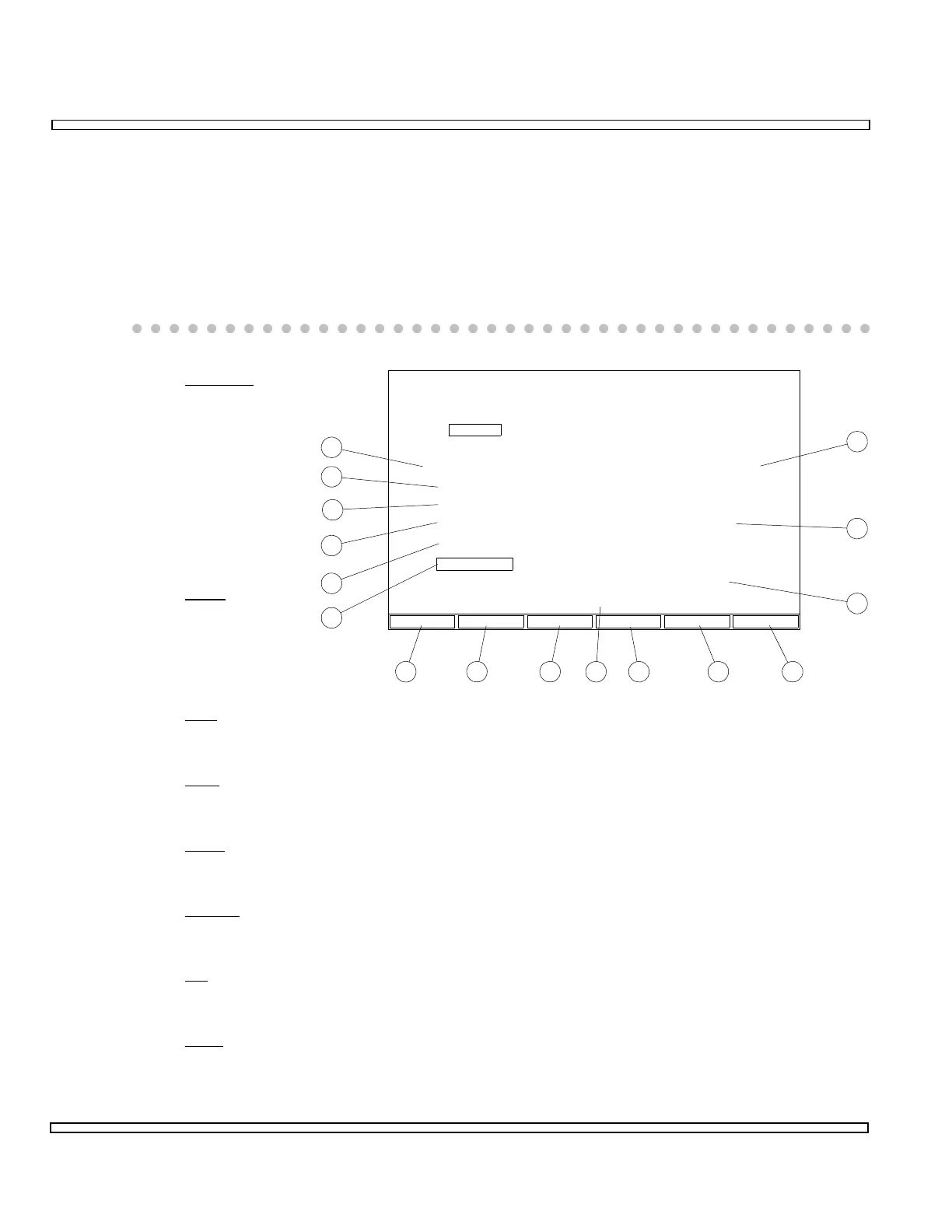
The Mobile Init (Initiated) Test requires a call to be initiated from the Mobile Phone. To
perform the Mobile Init Test, press F2 MOBILE from AMPS Manual Test Menu. “Place
Call” prompt appears.
Place call using Mobile Phone under test.
Once a connection is made, the Mobile Init Screen appears containing data.
8. Freq Err
Displays
Reverse Voice
Channel
Frequency
and
Frequency
Error received
from Mobile
Phone.
9. PWR
Displays
output power
received from
Mobile Phone.
10. Dev
Displays the SAT Deviation or Audio Deviation received from the Mobile Phone.
11. Quit
Press F6 QUIT to exit Manual Mobile Init Screen.
12. Start
Initiates test at cursor location.
13. SINAD
Accesses SINAD Meter for use with Cellular Testing.
14. AF
Displays SAT Frequency received from the Mobile Phone.
15. DVM
Accesses SINAD Meter for use with Cellular Testing.
8
9
10
1112131617 1415
18
19
20
21
22
23
8717124
QUIT
AMPS Cellular
Manual Test
Registration
Mobile Init
Cell Init
Called Adr:
Handoff Test
Pwr Level Test
SAT Test 5970 Hz
300
3
6823819
MAINTENANCECall Processing
Signal Tone Test
FREQ ERR
0.336 kHz
PWR
AF
5.970 kHz 2.36 kHz
Dev
834.000336 kHz
21.9 dBm
STARTSINADDVMANALYSCOPE

Table of Contents

Question and Answer IconNeed help?

Do you have a question about the IFR COM-120C and is the answer not in the manual?

IFR COM-120C Specifications

General IconGeneral
Resolution1 Hz
RF Input Impedance50 Ω
Third Order Intercept (TOI)+10 dBm
Display TypeLCD
Display Resolution640 x 480 pixels
RF Input Protection1 W
Power Requirements100-240 VAC, 50-60 Hz
Input VSWR1.5:1
Phase Noise-80 dBc/Hz @ 10 kHz offset

Summary

COM-120C Communications Service Monitor Operation Manual

Preface

Provides an overview of the manual's organization, scope, and intended audience.

Section 1: Introduction

Introduces the COM-120C, its functions, and basic operation modes.

Section 2: Installation

Provides information on preparing the COM-120C for use and operating precautions.

Section 3: Composite Controls

Details front and rear panel controls, screens, soft function keys, and menus for system interaction.

Section 4: Operation Procedures

Covers configuring and performing various operational tests like RF Generate, Receive, and Duplex modes.

Section 5: Common Practices

Offers suggestions for equipment and screen setups for common RF Generate and Receive practices.

Section 6: Options and Features

Describes optional features and accessories for the COM-120C, including testing capabilities.

Safety and Precautions

General Safety Warnings

Covers high voltage equipment hazards, servicing, case removal, and safety identification terms.

Battery Handling and ESD Precautions

Provides warnings for sealed lead-acid battery use and precautions for handling ESD-sensitive parts.

Appendix A: User I/O Connectors and Pin-Outs

Table of I/O Connectors

Details the connector names, types, signal direction, and signal types for COM-120C I/O ports.

Connector Pin-Out Tables

Provides specific pin assignments for MIC/ACC, GPIB, and RS-232 connectors.

Appendix B - Abbreviations

Soft Function Key Descriptions

An alphabetical reference for COM-120C soft function keys and their descriptions.

Appendix C - Repacking for Shipping

Shipping and Repacking Procedures

Details authorization, tagging, container requirements, freight costs, and step-by-step repacking instructions.

Index

Index-1

Alphabetical listing of topics and their corresponding page numbers for easy reference.