6-29
SECTION 6
OPTIONS
6-12-6 LTR TRUNKING RADIO SIMULATION
00607239
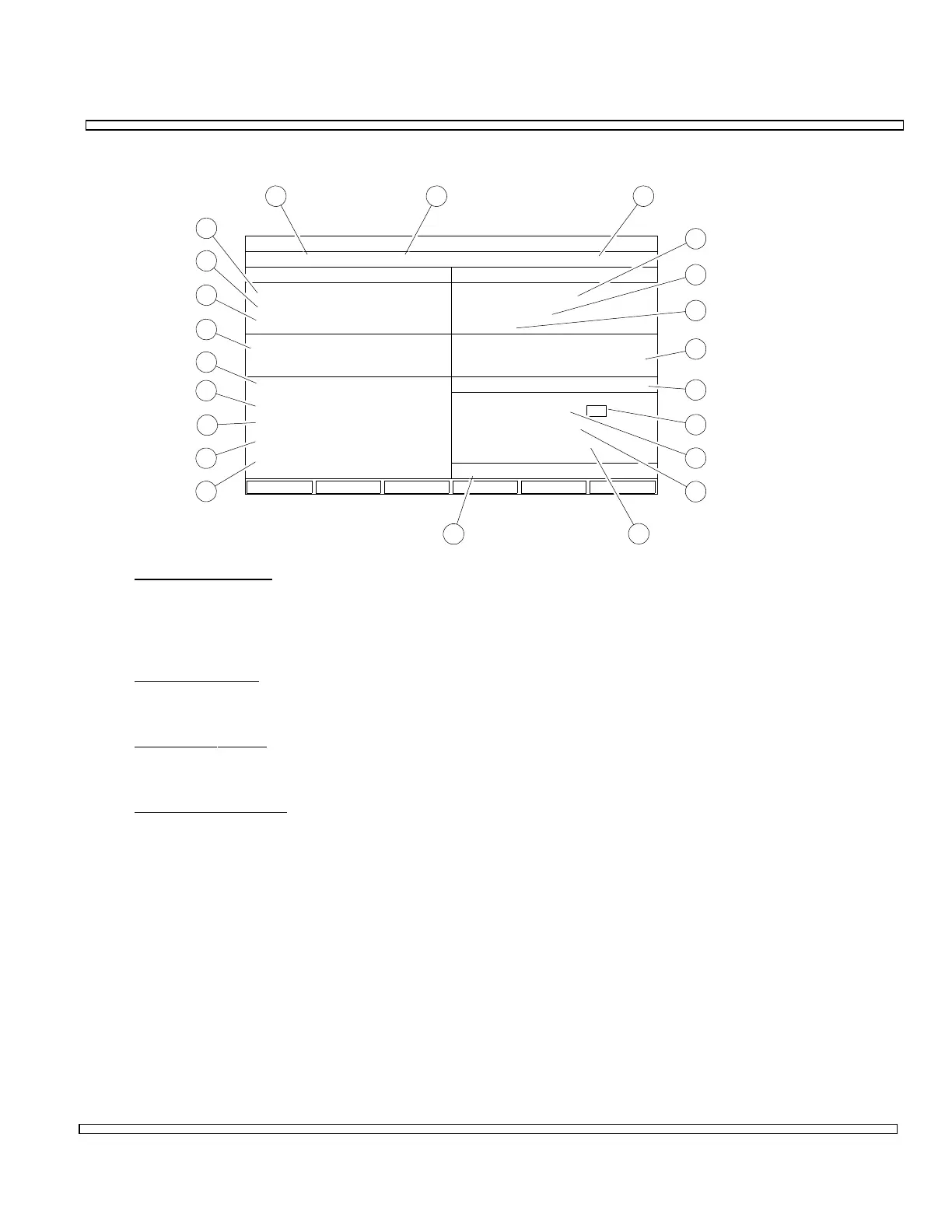
LTR TRUNKING RADIO SIMULATOR
Ch #: 1 Band: 800 MHz
RF:
Atten:
Input:
Free
Home
Area Goto
Group Group
In UseArea
Home
Free
1
10
1
2 PTT OFF
T/R
0 dB
851.0125 MHz MHz806.0125
-40.0 dBm
T/ROutput:
Level:
RF:
GEN-1 DATA
Shad:
Mod Source:
Deviation:
Frequency: 1000.0 Hz
0.0 kHz:
GEN1 FM
RF Power:
RF Error Freq:
Deviation:
AF Frequency:
Distortion:
0.0 mW
2.774 kHz
7.74 kHz (v)
1919 Hz
+ + + %
4
5
6
7
8
9
10
11
12
13
14
15
16
17
18
19
20
21
22
RECEIVE GENERATE
Extended Meas:
1 2 3
1. Channel Number
Displays Trunking Channel Number. Selections range from 1 to 760. Selection of
Channel Number and Band Selection (2) is used to set Generate RF Field (4) and
Receive RF Field (22).
2. Band Selection
Displays Trunking Band Selection. Displays 800 or 900 MHz.
3. Extended
Meas:
Allows for Extended Measurements.
4. Generate
RF Field
Displays RF Generate Frequency of COM-120C. Value is dependent on Channel
Number (1) and Band Selection (2). Band automatically changes to USER if this
field is edited. Formula for figuring value is as follows where Ch # is Channel
Number (1):
800 MHz Band Selection (2)
Frequency (MHz) = 806.0125 + [.025 x (Channel # - 1)]
900 MHz Band Selection (2)
Frequency (MHz) = 896.0125 + [.0125 x (Channel #-1)]