EasyManua.ls Logo

IFR COM-120C User Manual

IFR COM-120C
326 pages
To Next Page IconTo Next Page
To Previous Page IconTo Previous Page
Page #142 background image
4-69
SECTION 4
OPERATION
4-7 METERS OPERATION
The Independent Meters are independent of all other Operation Modes.
Pressing the MTRS INSTRUMENTS Key accesses the Independent Meters Menu.
From the Meters Menu, cursor to the number of the desired meter and press ENTER.
For Audio Frequency Counter Operation, see page 4-51.
For SINAD Meter Operation, see page 4-13.
For Digital Voltmeter Operation, see page 4-69.
For Distortion Meter Operation, see page 4-16.
The intention is to provide sufficient information to allow the operator to effectively use
the COM-120C to perform specific operator defined tests.
4-7-1 DIGITAL VOLTMETER OPERATION
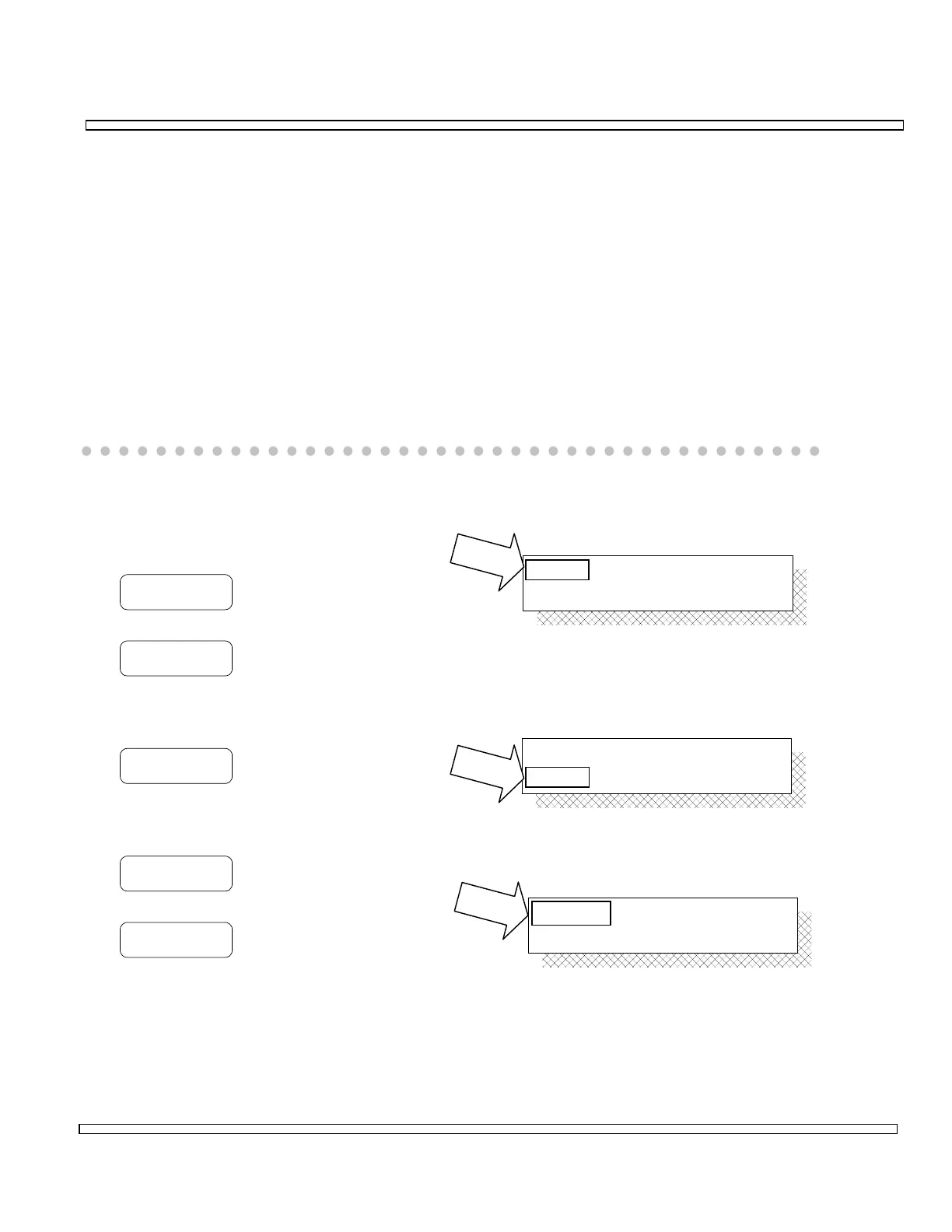
Select Source as follows:
MENU
Accesses a menu of available selections.
DC ZERO
Performs DC Zero when source is SCP/ DVM DC.
Select Range as follows:
MENU
Accesses a menu of available selections.
Select Peak Hold Function as follows:
OFF/ON
Toggles Peak Hold Function ON or OFF.
RST PK
Resets Peak Hold Function.
Source:
Range:
SCP/DVM AC
1 Volt
Source:
Range:
SCP/DVM AC
1 Volt
Peak Hold:
Average:
ON
ON 2

Table of Contents

Question and Answer IconNeed help?

Do you have a question about the IFR COM-120C and is the answer not in the manual?

IFR COM-120C Specifications

General IconGeneral
Resolution1 Hz
RF Input Impedance50 Ω
Third Order Intercept (TOI)+10 dBm
Display TypeLCD
Display Resolution640 x 480 pixels
RF Input Protection1 W
Power Requirements100-240 VAC, 50-60 Hz
Input VSWR1.5:1
Phase Noise-80 dBc/Hz @ 10 kHz offset

Summary

COM-120C Communications Service Monitor Operation Manual

Preface

Provides an overview of the manual's organization, scope, and intended audience.

Section 1: Introduction

Introduces the COM-120C, its functions, and basic operation modes.

Section 2: Installation

Provides information on preparing the COM-120C for use and operating precautions.

Section 3: Composite Controls

Details front and rear panel controls, screens, soft function keys, and menus for system interaction.

Section 4: Operation Procedures

Covers configuring and performing various operational tests like RF Generate, Receive, and Duplex modes.

Section 5: Common Practices

Offers suggestions for equipment and screen setups for common RF Generate and Receive practices.

Section 6: Options and Features

Describes optional features and accessories for the COM-120C, including testing capabilities.

Safety and Precautions

General Safety Warnings

Covers high voltage equipment hazards, servicing, case removal, and safety identification terms.

Battery Handling and ESD Precautions

Provides warnings for sealed lead-acid battery use and precautions for handling ESD-sensitive parts.

Appendix A: User I/O Connectors and Pin-Outs

Table of I/O Connectors

Details the connector names, types, signal direction, and signal types for COM-120C I/O ports.

Connector Pin-Out Tables

Provides specific pin assignments for MIC/ACC, GPIB, and RS-232 connectors.

Appendix B - Abbreviations

Soft Function Key Descriptions

An alphabetical reference for COM-120C soft function keys and their descriptions.

Appendix C - Repacking for Shipping

Shipping and Repacking Procedures

Details authorization, tagging, container requirements, freight costs, and step-by-step repacking instructions.

Index

Index-1

Alphabetical listing of topics and their corresponding page numbers for easy reference.