EasyManua.ls Logo

IFR COM-120C User Manual

IFR COM-120C
326 pages
To Next Page IconTo Next Page
To Previous Page IconTo Previous Page
Page #274 background image
6-99
SECTION 6
OPTIONS
6-15-2 SYSCODE CALCULATION
The system codeword is used when generating control channel signalling as a system
identifier. When testing Radio Units, the correct SYSCODE allows the RU under test to
go into service.
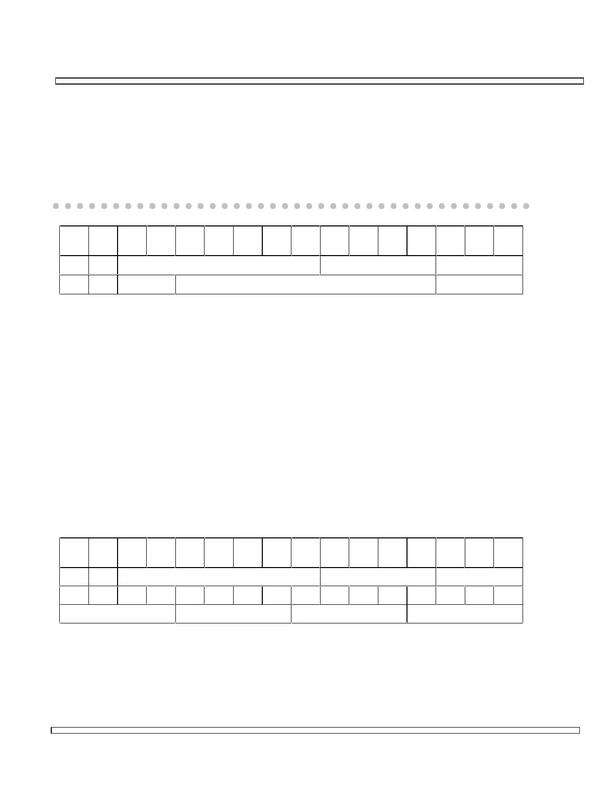
The SYSCODE is actually constructed from a number of different fields. The codeword
is 15 bits long with the most significant bit (B15) = 0.
B1
5
B1
4
B1
3
B1
2
B1
1
B1
0
B9 B8 B7 B6 B5 B4 B3 B2 B1 B0
00OPID NDD LAB
01OPID NDD LAB
B14 specifies whether the network is termed a National Network (1) or a Regional
Network (0). Depending on the setting of the Network type, the length of the OPID field
is either 7 bits or 2 bits and the NDD field 4 or 9 bits. The LAB field is normally set to
001 to allow any category radio unit to access the system.
The NDD field generally contains a site identifier number for a multiple site network.
The easiest way to construct the SYSCODE is to convert each field into binary with all
leading zeroes to complete the field width, then create a 16 bit hexadecimal number
converting each four bits into a hexadecimal character 0-9, A-F.
Example: A Radio Unit is programmed for a regional network, OPID=50, and has access
authorization for site area 1.
OPID = 94 decimal = 1011110 binary
NDD = 1 decimal = 0001
LAB = 001 SYSCODE = 2F09
B1
5
B1
4
B1
3
B1
2
B1
1
B1
0
B9 B8 B7 B6 B5 B4 B3 B2 B1 B0
00OPID NDD LAB
0010111100001001
2F09
In many instances where the Radio Unit has unlimited access, authorization NDD may
be set to any value.

Table of Contents

Question and Answer IconNeed help?

Do you have a question about the IFR COM-120C and is the answer not in the manual?

IFR COM-120C Specifications

General IconGeneral
Resolution1 Hz
RF Input Impedance50 Ω
Third Order Intercept (TOI)+10 dBm
Display TypeLCD
Display Resolution640 x 480 pixels
RF Input Protection1 W
Power Requirements100-240 VAC, 50-60 Hz
Input VSWR1.5:1
Phase Noise-80 dBc/Hz @ 10 kHz offset

Summary

COM-120C Communications Service Monitor Operation Manual

Preface

Provides an overview of the manual's organization, scope, and intended audience.

Section 1: Introduction

Introduces the COM-120C, its functions, and basic operation modes.

Section 2: Installation

Provides information on preparing the COM-120C for use and operating precautions.

Section 3: Composite Controls

Details front and rear panel controls, screens, soft function keys, and menus for system interaction.

Section 4: Operation Procedures

Covers configuring and performing various operational tests like RF Generate, Receive, and Duplex modes.

Section 5: Common Practices

Offers suggestions for equipment and screen setups for common RF Generate and Receive practices.

Section 6: Options and Features

Describes optional features and accessories for the COM-120C, including testing capabilities.

Safety and Precautions

General Safety Warnings

Covers high voltage equipment hazards, servicing, case removal, and safety identification terms.

Battery Handling and ESD Precautions

Provides warnings for sealed lead-acid battery use and precautions for handling ESD-sensitive parts.

Appendix A: User I/O Connectors and Pin-Outs

Table of I/O Connectors

Details the connector names, types, signal direction, and signal types for COM-120C I/O ports.

Connector Pin-Out Tables

Provides specific pin assignments for MIC/ACC, GPIB, and RS-232 connectors.

Appendix B - Abbreviations

Soft Function Key Descriptions

An alphabetical reference for COM-120C soft function keys and their descriptions.

Appendix C - Repacking for Shipping

Shipping and Repacking Procedures

Details authorization, tagging, container requirements, freight costs, and step-by-step repacking instructions.

Index

Index-1

Alphabetical listing of topics and their corresponding page numbers for easy reference.