i~.
87C51GBHARDWARE DESCRIPTION
remainsunchanged,but the POSF’Rgets 1swritten to
it.
If a PI throughP5 latch containsa 1,then the output
levelis controlledby the signallabeled“alternate out-
put function.”The pin levelis alwaysavailableto the
pin’salternate input function,if any.
Ports 1 through 5 have internal pullupa.Port O has
opendrainoutputs.Each 1/0 linecanbeindependently
usedas aninputor an output(PortsOand2maynot be
used as general purpose 3/0 when beingused as the
ADDRBWDATA BUS).To be usedas an inpuLthe
port bit latch must contain a 1, which turns off the
output driver PET. On Ports I through 5 the pin is
pulled high by the internal pullup, but can be pulled
lowby an externalsource.
PI, P2, P4, and P5 reset to a lowstate. Whilein reset
these pins can sink large amountsof current. If these
ports are to be used as inputs and externallydriven
highwhilein reset,the usershouldbeawareofpossible
contention.A simplesolutionis to use opencollector
interfaceswiththeseport pinsor to bufferthe inputs.
Port Odiffersfromthe other ports in not havinginter-
nal puliups.The pullupFET in the POoutputdriveris
usedonlywhenthe port is emitting 1sduringexternal
memory acceses.
otherwise the pullup FET is off.
ConsequentlyPOlines that are being used as output
port linesare opendrain. Writing a 1 to the bit latch
leavesboth output FBTs off, which floatsthe pin and
allowsit to beusedas a high-impedanceinput.Because
Ports 1 through5 have freedinternal pullupsthey are
sometirneacalled“quasi-bidirectional”porta.
When configuredas inputs they pull high and will
sourcecurrent (IILin the data sheets)whenexternally
pulled low. Port O, on the other hand, is considered
“true” bidirectional,becauseit floats whenconfigured
as an input.
ThelatchesforportsOand 3have 1swrittento them by
the reset function.If a Ois subsequentlywritten to a
port latch, it canbe reconfiguredas an inputbywriting
a 1to it.
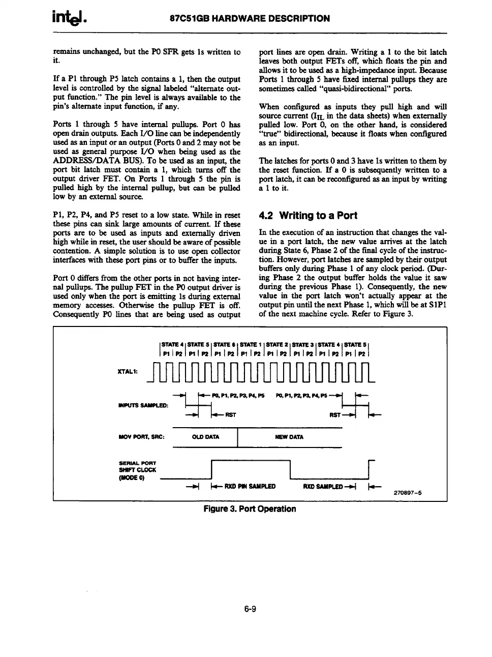
4.2 Writing to a Port
In theexecutionofaninstructionthatchangeatheval-
uein a portlatch,thenewvaluearrivesat thelatch
duringState6,Phase2ofthefti cycleoftheinstruc-
tion.Howewr,port latch= are sampledbytheir output
bufkrs onlyduringPhase 1ofany clockperiod.(Dur-
ing Phase 2 the output buffer holds the value it saw
during the previousPhase 1). Consequently,the new
value in the port latch won’t actually appear at the
outputpinun~ilthe nextPhaac 1,which~ beat SIPI
of the next machinecycle.Refer to Figure3.
SIAIE4 STA7E.5 STATE6 SIAIE1 STATE2 SIAIE3 STATE4 STATE5
lPllmlmlmlmlnlPl lnlml*Imlmlmlml Pllml
XTAL1:
VI-.
PO.P1,PZ,PS,P4,P6 PO,P1,PZ,P3.P4,P6
wu?a aAnPLEo:
=
UovPORT,SRC: OLOOATA
I
NEW
OATA
iiiEF~
+
+RXDPINSANIUO
RXOSAMPUO+ k-
270S97-5
Figure3. PortOperation
6-9