i~.
87C51GB HARDWARE DESCRIPTION
Table4.TMOD:Timer/CounterModeControlRedeter
TMOD
Symbol
GATE
c/T
Ml MO
00
01
10
11
11
Address= 89H
ResetValue= 0000OOOOB
NotBitAddressable
TIMER1
I
TIMERO
I GATEI C/7 [ Ml I MO I GATEI C/~ I Ml I MO I
Bit 7 6 5
4
3
2 1 0
Funotion
Gatingcontrolwhenset.Timer/CounterOor1isenabledonlywhileINTOor~ pin
ishighandTROorTRl controlpinisset.Whencleared,17merOor1isenabled
wheneverTROorTRl controlbitisset.
TimerorCounterSelector.ClearforTimeroperation(inputfrominternalsystem
clock).SetforCounteroperation(inputfromTOorT1inputpin).
OperatingMode
8-bitTimer/Counter.THxwithTLxas5-bitpresceler.
16-bitTimer/Counter.THxandTLxarecascaded;thereisnoprescaler.
8-bitauto-reloadTimer/Counter.THxholdsavaluewhichistobereloadedintoTLx
eachtimeitoverflowa.
(TimerO)TLOisan8-bitTimer/CountercontrolledbythestandardTimerOcontrol
bite.THOisan8-bittimeronlycontrolledbyTimer1controlbits.
(Timer1)Timer/Counterstopped.
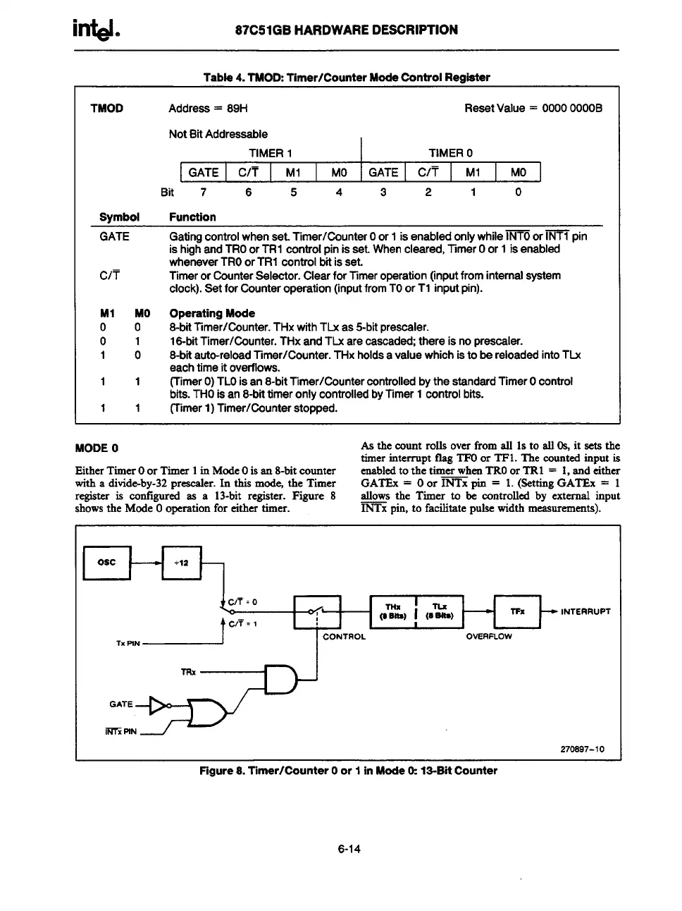
MODEO
Asthecountrolls overfromall 1sto all 0s, it sets the
timerinterrupt flagTFUor TF1. The countedinput is
EitherTimerOor Timer 1in ModeOisan 8-bitcounter enabledto the timer whenTROor TRl = 1,and either
witha divid&by-32preaesler.In this mb the Timer
GATEx = Oor INTx pin = 1.(8ettingGATEx = 1
regiSteris cotilgur~ as
a 13-bit register. Figure 8
allowsthe Timer to & controlled by-external input
showsthe ModeOoperationfor either timer.
~ pin, to facilitate pulsewidthmeasurements).
I
Osc
1 <,1
1 ICO!TROLI”TL’ !(”=)HOWWX F
1
INTERRUPT
270897-10
Figure8. Timer/CounterOor 1inMode1%13-BitCounter
6-14