i~.
87C51GBHARDWARE DESCRIPTION
TRxand TFx are controlbits in the SFRTCON.The
MODE1
GATExbitsarein TMOD. There are two different
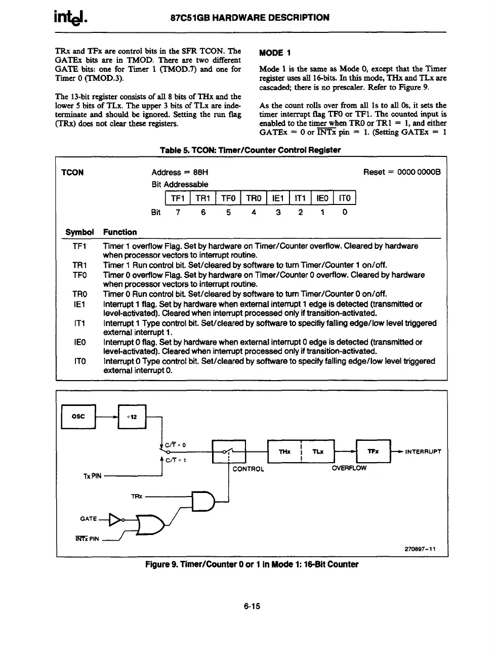
GATE bits: one for Timer 1 (TMOD.7)and one for Mode 1 is the same as Mode 0, exeeptthat the Timer
TimerO(TMOD.3).
registerusesall Id-bits.In this mode,THxand TLxare
cascaded;thereis no presesler. Refer to Figure9.
The 13-bitregisterconsistsof all 8bitsof THx and the
lower5bits of TLx.The upper 3 bits of TLx are inde
As the countrolls overfrom all 1sto all 0s, it sets the
terminateand should be imored. %ttin~ the run tlaiz
timer interrupt fhz TFOor TF1. The countedinput is
(TRx)doesnot clear these-registers. - -
enabledto th~tim~rwhenTROor TRl = 1,and~ther
GATEx = Oor INTxpin = 1. (SettingGATE%= 1
Table5.TCON:Timer/CounterControlRegister
TCON
Address= 88H
Reset= 0000OOOOB
BitAddressable
TF1 TR1 TFO TRO IEI IT1 IEO ITO
Bfi 7 6 5 4 3 2 1 0
Symbol Function
TF1 Timer1overflowFlag.SetbyhardwareonTimer/Countaroverflow.Clearedbyhardware
whenprocessorvectoratointerruptroutine.
TR1 Timer1 Runcontrolbit.Set/clesredbysoftwaretoturnTimer/Counter1on/off.
TFO TimerOoverflowFlag.SetbyhardwareonTimer/CounterOoverflow.Clearedbyhardware
whenprocessorvectorstointerruptroutine.
TRO TimerORuncontrolbit.Set/clearedbysoftwaretoturnlimer/CounterOon/off.
IE1
Interrupt1flag.Setbyhardwarewhenexternalinterrupt1edgeisdetected(transmittedor
level-activated).Clearedwheninterruptprocessedonlyiftransition-activated.
IT1
Interrupt1Typecontrolbit.Set/clearedbysoftwaratospecifiyfallingedge/lowleveltriggered
externalinterrupt1.
IEO InterruptOflag.SetbyhardwarewhenexternalinterruptOedgeisdetected(transmittedor
level-activated).Clearedwheninterruptprocessedonlyiftransition-activated.
ITO InterruptOTypecontrolbit.Set/clearedbyaoftwaretospecifyfallingedge/lowleveltriggered
externalinterruptO.
Osc
I
270S97-11
Figure9.Timer/CounterOor 1InMode1:16-BitCounter
6-15