i@.
87C51GBHARDWARE DESCRIPTION
allows the Timer to be mntrolled by external input
(SettingGATEx= 1allowsthe Timerto becontrolled
IIVTXpinto facilitatepuke width measurements).
by external input INTx pin, to facilitate pulse width
measurements).
TRx and TFx are controlbits in the SRF TCGN.The
GATEx bits are in TMOD. There are two different
~ and TFx are control bits in the SFR TCON.The
GATE bits: one for Timer 1 (TMOD.7)and one for
GATEx bits are in TMOD. There are two different
TimerO(TMOD.3).
GATE bits: one for Timer 1 (TMOD.7)and one for
Timer O(TMOD.3).
MODE2
MODE3
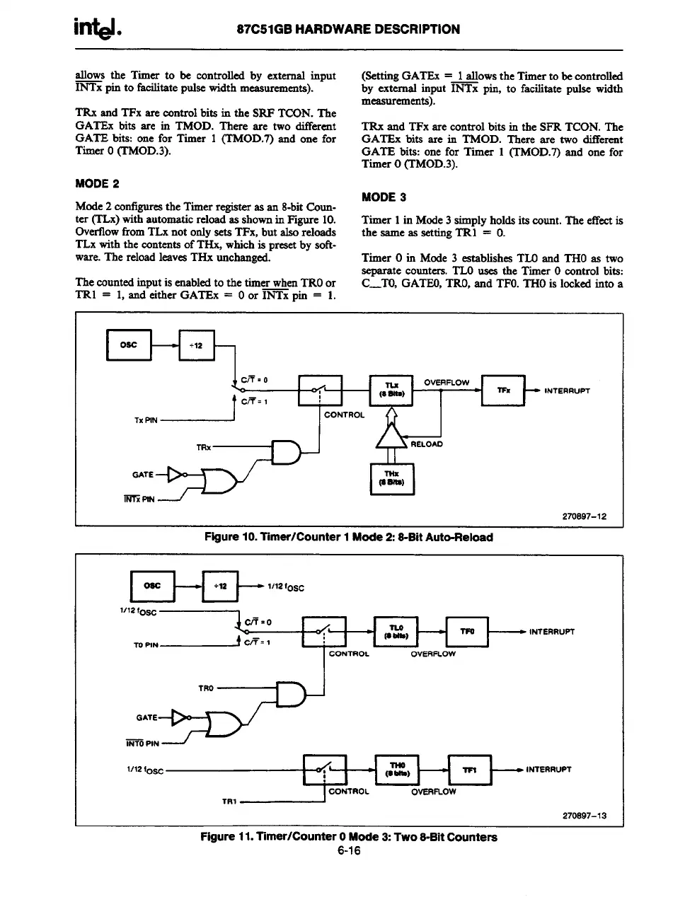
Mode2configurestheTimerregisteras an 8-bitCoun-
ter (TLx)withautomaticreloadas shownin F@re 10.
Timer 1in Mode3 simplyholdsits count.The effectis
OvertlowfromTLxnot onlysets TFx, but alsoreloads
the same as settingTRl = O.
TLxwiththe contentsofTHx, whichis presetby soft-
ware.The reloadleavesTHxunchanged.
Timer Oin Mode 3 establishesTLOand THOas two
smarate counters.TLOuses the Timer Ocxmtrolbits:
Thecountedinputis enabledto the timer whenTROor
C2T0, GATEO,TRO,and TFO.THOis lockedinto a
TRl = 1,and either GATEx = Oor INTx pin = 1.
I
Oac
1+ I
,X.NJ::: ‘
L
‘C’JJ
INTERRuPT
TRx
GATE
Tffx
(aalfs)
immti
I
270897-12
Figure10.Timer/Counter1Mode2:S-BitAuto-Reload
IOSCH t-
+ls
1/12lo~~
l/12fo=
1~1
.F.,N~@’1 I :
INTERRUPT
CONTROL
OVERFLOW
l/12 foa~
I -G 1
INTERRUPT
CONTROL
TR1
OVERFLOW
270897-13
Figure11.Tmer/CounterOMode3:Two8-BitCountere
6-16