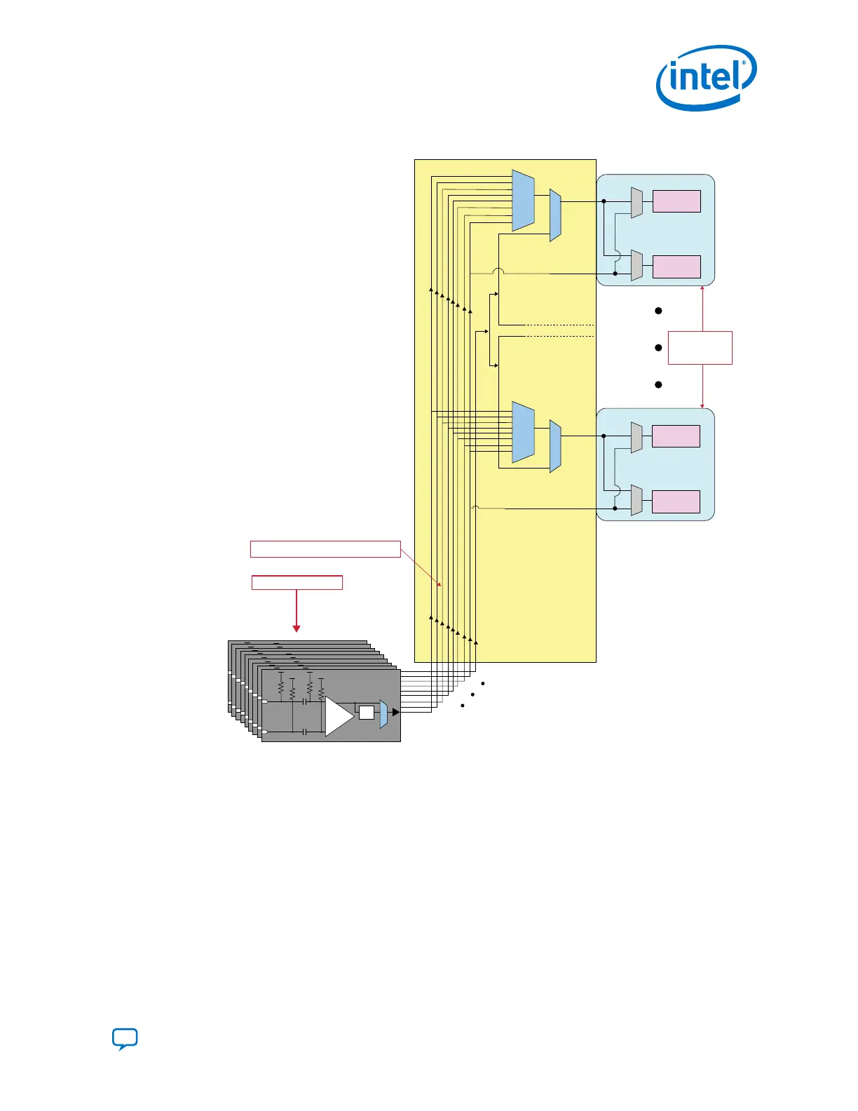
Figure 10. Reference Clock Access
Transmitter
Receiver
Transmitter
Receiver
Transceiver
Transceiver
Reference Clock
Channels
23 to 0
Reference clock network within an E-Tile
Nine REFCLK LVPECL Pins
REFCLK_0
refclk_in_A
refclk_in_B
refclk_in_A
refclk_in_B
REFCLK_8
+
–
Divide
by 2
LVPECL
+
–
Divide
by 2
LVPECL
+
–
Divide
by 2
LVPECL
+
–
Divide
by 2
LVPECL
+
–
Divide
by 2
LVPECL
+
–
Divide
by 2
LVPECL
+
–
Divide
by 2
LVPECL
+
–
Divide
by 2
LVPECL
+
–
Divide
by 2
LVPECL
The reference clock network spans across the entire transceiver tile. If the design
requires a single reference clock to be supplied to more than one transceiver tile, you
must route the reference clock to multiple tiles on the printed circuit board (PCB).
1. Intel
®
Stratix
®
10 E-Tile Transceiver PHY Overview
UG-20056 | 2019.02.04
Send Feedback
Intel
®
Stratix
®
10 E-Tile Transceiver PHY User Guide
17