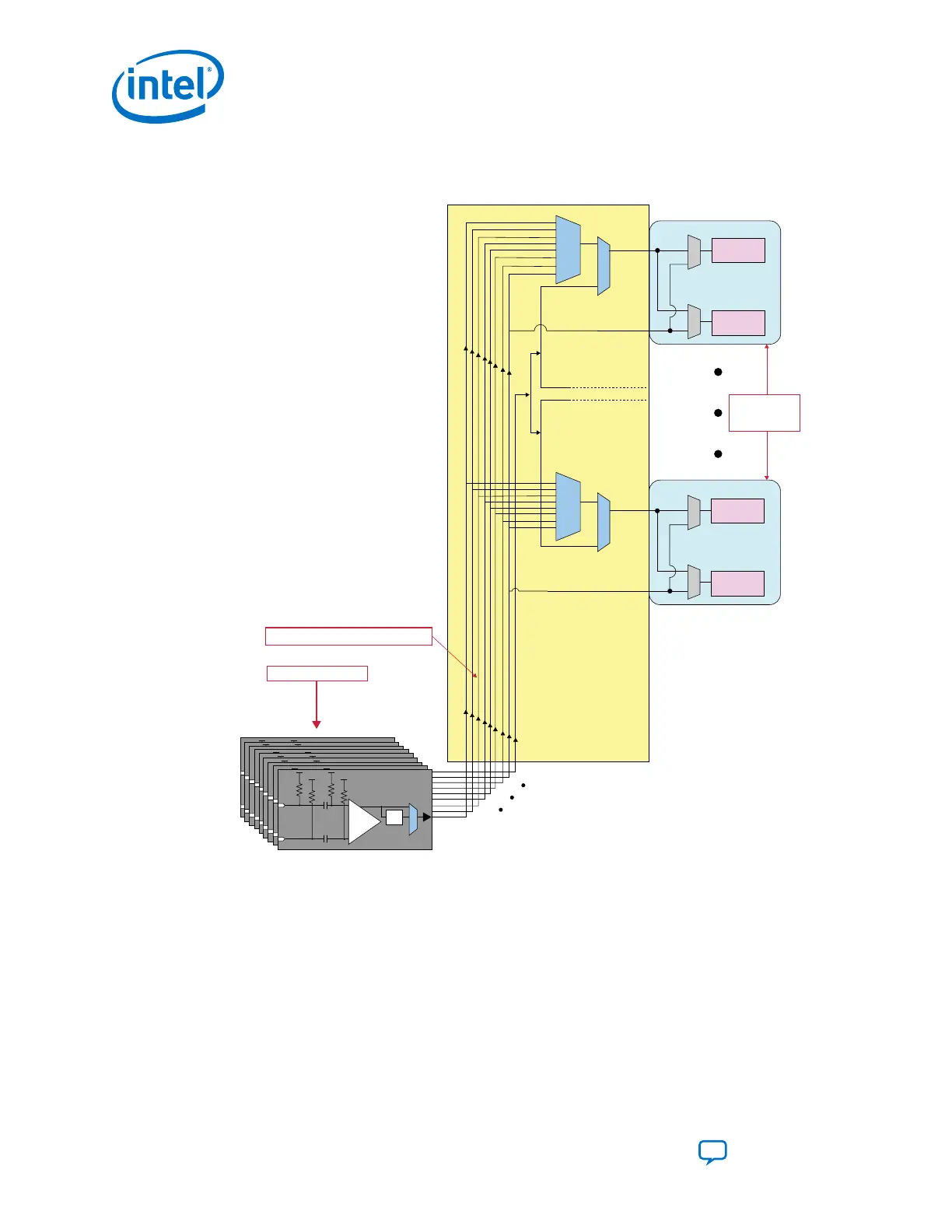
Figure 50. REFCLK LVPECL Pins
This diagram illustrates the nine refclk pins and the reference clock network within a given Intel Stratix 10 E-
Tile.
Transmitter
Receiver
Transmitter
Receiver
Transceiver
Transceiver
Reference Clock
Channels
23 to 0
Reference clock network within an E-Tile
Nine REFCLK LVPECL Pins
REFCLK_0
refclk_in_A
refclk_in_B
refclk_in_A
refclk_in_B
REFCLK_8
+
–
Divide
by 2
LVPECL
+
–
Divide
by 2
LVPECL
+
–
Divide
by 2
LVPECL
+
–
Divide
by 2
LVPECL
+
–
Divide
by 2
LVPECL
+
–
Divide
by 2
LVPECL
+
–
Divide
by 2
LVPECL
+
–
Divide
by 2
LVPECL
+
–
Divide
by 2
LVPECL
For details on LVPECL standard spec, refer to Intel Stratix 10 Device Datasheet.
Related Information
• PMA Analog Reset on page 104
• Register Map on page 165
• Intel Stratix 10 Device Datasheet
• Intel Stratix 10 Device Family Pin Connection Guidelines
• My Intel support
4. Clock Network
UG-20056 | 2019.02.04
Intel
®
Stratix
®
10 E-Tile Transceiver PHY User Guide
Send Feedback
88