•
For the cooling system to function properly, the airflow around the chassis must be
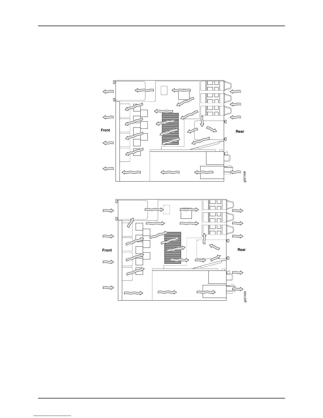
unrestricted. See Figure 30 on page 82 and Figure 31 on page 82.
Figure 30: Back-to-Front Airflow
Figure 31: Front-to-Back Airflow
•
If you are mounting the switch on a rack or cabinet along with other equipment, ensure
that the exhaust from other equipment does not blow into the intake vents of the
chassis.
•
Leave at least 6 in. (15.2 cm) clearance on the front and the back of the chassis for
airflow.
•
Leave at least 6 in. (15.2 cm) clearance on the left of the chassis for installing the
grounding lug.
•
Leave at least 24 in. (61 cm) clearance on front and of the switch for service personnel
to remove and install hardware components. See Figure 32 on page 83.
Copyright © 2015, Juniper Networks, Inc.82
EX4550 Switch Hardware Guide