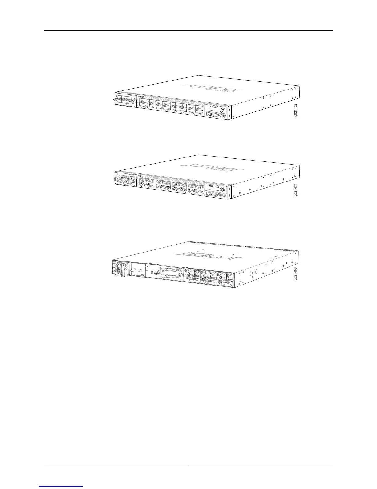
Figure 1: Front Panel of an EX4550-32F Switch
Figure 2 on page 5 shows the front panel of an EX4550-32T switch.
Figure 2: Front Panel of an EX4550-32T Switch
Figure 3 on page 5 shows the rear panel of an EX4550 switch with power supplies and
fan modules installed.
Figure 3: Rear Panel of an EX4550 Switch
To provide carrier-class reliability, EX4550 switches include:
•
Dual redundant, load-sharing power supplies that are hot-insertable and hot-removable
field-replaceable units.
•
Three fan modules, which are field-replaceable units (FRUs).
•
Redundant Routing Engines in a Virtual Chassis configuration. This redundancy enables
graceful Routing Engine switchover (GRES).
•
Junos OS with its modular design that enables failed system processes to gracefully
restart.
Optional Modules
EX4550 switches support four types of optional modules: an 8-port 10-Gigabit Ethernet
SFP+ expansion module, an 8-port 10GBASE-T expansion module, a 2-port 40-Gigabit
Ethernet QSFP+ expansion module, and a 128-Gigabit Virtual Chassis module. You can
install up to two modules,in any combination of these modules, one in each of the module
slots. There is one module slot on the front panel and one on the rear panel of the switch.
5Copyright © 2015, Juniper Networks, Inc.
Chapter 1: System Overview