•
See Rear Panel of an EX3300 Switch.
•
See Rear Panel of an EX4200 Switch.
•
See EX4300 Switches Hardware Overview
•
See Front Panel of an EX4500 Switch.
•
See “EX4550 Switches Hardware Overview” on page 3
•
See Switch Fabric and Routing Engine (SRE) Module in an EX6200 Switch.
•
See Switch Fabric and Routing Engine (SRE) Module in an EX8208 Switch.
•
See Routing Engine (RE) Module in an EX8216 Switch.
•
See Front Panel of an XRE200 External Routing Engine.
•
See Management Panel of an EX4600 Switch
•
OCX1100 Switches Hardware Overview
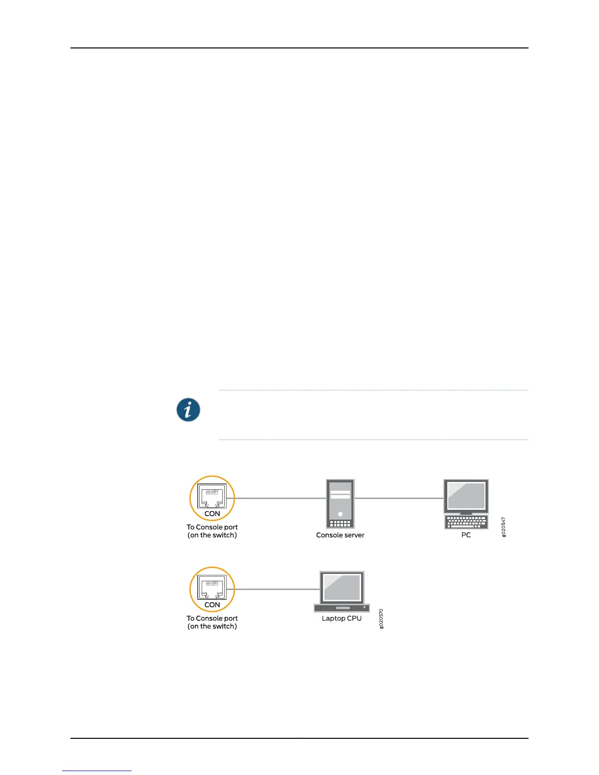
2. Connect the other end of the Ethernet cable into the console server (see
Figure 50 on page 172) or management console (see Figure 51 on page 172).
To configure the device from the management console, see “Connecting and Configuring
an EX Series Switch (CLI Procedure)” on page 187 or “Connecting and Configuring an EX
SeriesSwitch (J-Web Procedure)” on page 190 or Connecting and Configuring an OCX1100
Switch (CLI Procedure).
NOTE: EX2200-24T-4G-DC and OCX1100 switches do not support switch
connection and configuration through the J-Web interface.
Figure 50: Connecting a Switch to a Management Console Through a
Console Server
Figure 51: Connecting a Switch Directly to a Management Console
Related
Documentation
Configuring the Console Port Type (CLI Procedure)•
• Connecting a Switch to a Network for Out-of-Band Management on page 169
• Console Port Connector Pinout Information for an EX Series Switch on page 123
Copyright © 2015, Juniper Networks, Inc.172
EX4550 Switch Hardware Guide