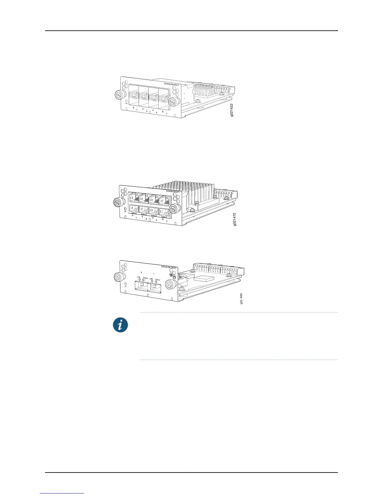
Figure 8: 8-Port SFP+ Expansion Module
The SFP+ expansion module can operate either in 10-gigabit or in 1-gigabit mode. The
operating mode for an SFP+ expansion module is shown in the output of the show chassis
pic fpc-slot slot number pic-slot slot number command.
Figure 9 on page 24 shows the 10GBASE-T expansion module.
Figure 9: 8-Port 10GBASE-T Expansion Module
Figure 10 on page 24 shows the QSFP+ expansion module.
Figure 10: 2-Port QSFP+ Expansion Module
NOTE: When you install an expansion module in the switch or replace an
expansion module with another expansion module, the switch detects the
ports on the expansion module. The switch creates the required interfaces
when transceivers are installed in these ports.
Each expansion module has an LED on the faceplate (labeled ST). It indicates the status
of the expansion module.
Figure 11 on page 25 shows the location of LEDs on the SFP+ expansion module.
Copyright © 2015, Juniper Networks, Inc.24
EX4550 Switch Hardware Guide