•
ESD grounding strap
•
Phillips screwdriver, number 2
•
A replacement optional module or cover panel
•
An antistatic bag or antistatic mat
CAUTION: We recommend that you install either a replacement optional
moduleor a cover panel in the empty module slot to avoidchassisoverheating
and dust accumulation.
To remove an expansion module from the switch (see Figure 64 on page 212,
Figure 65 on page 213, and Figure 66 on page 213):
1. Attach the ESD grounding strap to your bare wrist, and connect the strap to the ESD
point on the chassis.
2. Unscrew both captive screws on the faceplate of the expansion module by using your
fingers. If you are unable to unscrew the captive screws by using your fingers, use the
screwdriver.
3. Hold both the captive screws and gently pull the expansion module outward and out
of the module slot.
4. Place the expansion module in an antistatic bag or on an antistatic mat placed on a
flat, stable surface.
5. If you are not replacing the expansion module with an optional module, install the
cover panel over the slot.
NOTE: After you have removed an expansion module, wait for at least 5
seconds before you install an expansion module. If you do not wait for at
least 5 seconds, the interfaces on the expansion module might not come
up.
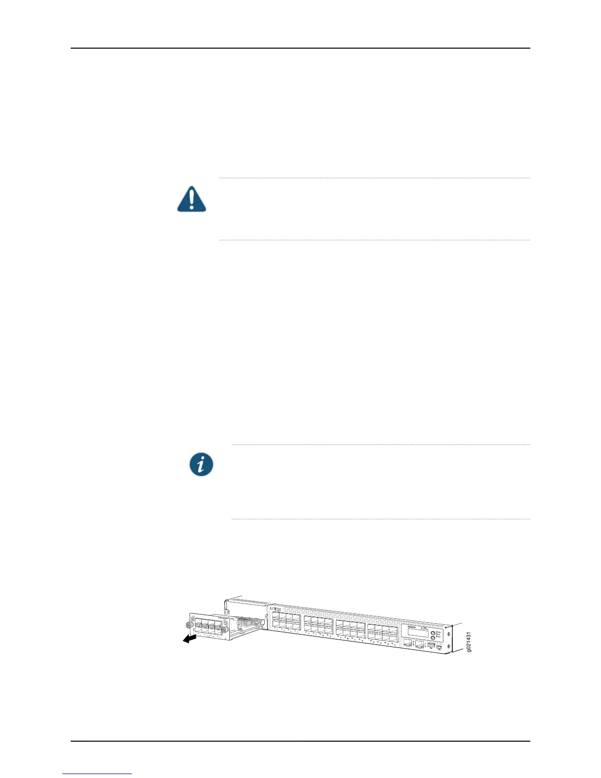
Figure 64 on page 212 shows removing an SFP+ expansion module from the front panel
of an EX4550–32F switch.
Figure 64: Removing an SFP+ Expansion Module from an EX4550-32F
Switch
Figure 65 on page 213 shows removing a 10GBASE-T expansion module from the front
panel of an EX4550-32T switch.
Copyright © 2015, Juniper Networks, Inc.212
EX4550 Switch Hardware Guide