4. Taking care not to touch power supply pins, leads, or solder connections, remove the
power supply from the bag.
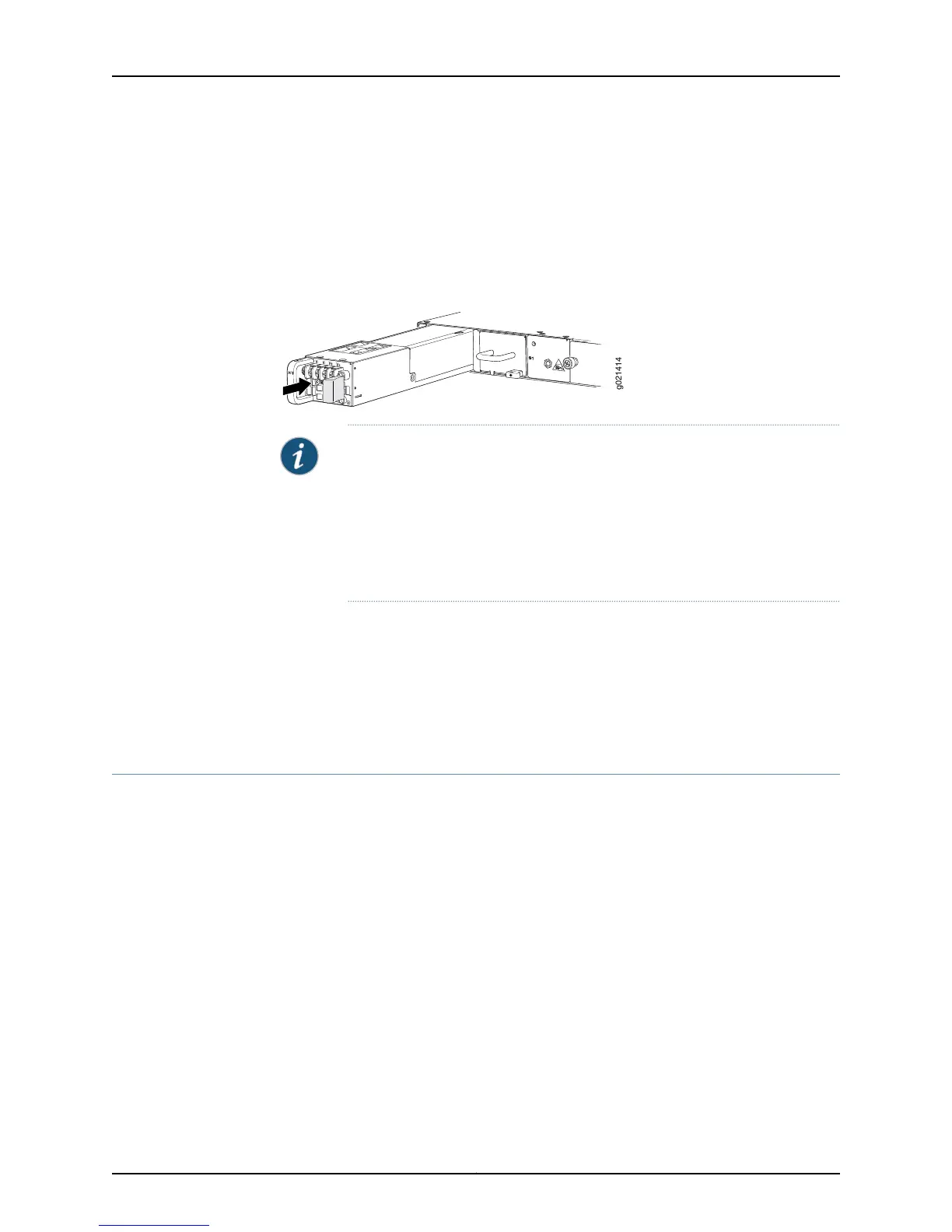
5. Using both hands, place the power supply in the power supply slot on the rear panel
of the switch and slide it in until it is fully seated and the ejector lever fits into place.
You will hear a distinct click when the power supply is fully seated in the chassis.
Figure 59: Installing a DC Power Supply in an EX4550 Switch
NOTE: If you have a Juniper J-Care service contract, register any addition,
change, or upgrade of hardware components at
https://www.juniper.net/customers/csc/management/updateinstallbase.jsp .
Failure to do so can result in significant delays if you need replacement parts.
This note applies if you change the type of power supply or add a new type
of expansion module. It does not apply if you replace these components with
the same type of component.
Related
Documentation
Connecting DC Power to an EX4550 Switch on page 165•
• Removing a DC Power Supply from an EX4550 Switch on page 207
• DC Power Supply in EX4550 Switches on page 44
• EX4550 Switches Hardware Overview on page 3
Removing a DC Power Supply from an EX4550 Switch
The power supply in EX4550 switches is a hot-removable and hot-insertable
field-replaceable unit (FRU) installed in the rear panel of the switch: You can remove
and replace it without powering off the switch or disrupting switch functions.
Before you begin removing a power supply from the switch:
•
Ensure you understand how to prevent electrostatic discharge (ESD) damage. See
“Prevention of Electrostatic Discharge Damage” on page 287.
Ensure that you have the following parts and tools available to remove the power supply
from the switch chassis:
•
ESD grounding strap
•
Phillips (+) screwdriver, number 2
•
An antistatic bag or an antistatic mat
•
Replacement power supply or a cover panel for the power supply slot
207Copyright © 2015, Juniper Networks, Inc.
Chapter 17: Replacing Power Supply