VCPs of the Virtual Chassis module installed in the module slot on the front panel of the
chassis are displayed as VCP-1/0 and VCP-1/1 in the CLI. VCPs of the Virtual Chassis
module installed in the module slot on the rear panel of the chassis are displayed as
VCP-2/0 and VCP-2/1 in the CLI. A 255 appears in the interface name if this dedicated
VCP is part of a link aggregation group (LAG) bundle; for instance, a display of
VCP-255/1/0 indicates that VCP-1/0 is part of a LAG.
NOTE: Installing the Virtual Chassis module is not mandatory for using an
EX4550 switch in a Virtual Chassis configuration. You can also interconnect
EX4550 switches or connect EX4550 switches to EX4200 switches and
EX4500 switches through SFP+ expansion module ports or SFP+ network
ports configured as VCPs to form a Virtual Chassis. You can also configure
10GBASE-T network ports, 10GBASE-T expansion module ports, or QSFP+
expansionmoduleports asVCPstointerconnect EX4550 switchesin a Virtual
Chassis.
NOTE: Virtual Chassis module, Virtual Chassis cables, and Virtual Chassis
cable connector retainers are not part of the EX4550 switch shipping
configuration.If you want to purchase these, you mustorder them separately.
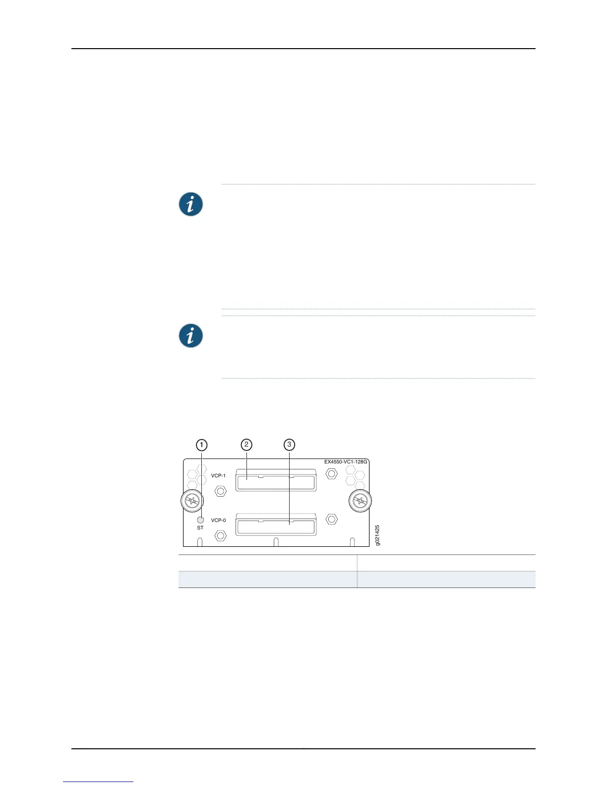
The Virtual Chassis module has an LED (labeled ST) on the left side of its faceplate. It
indicates the status of the Virtual Chassis module. See Figure 15 on page 27.
Figure 15: Virtual Chassis Module LED
EX4550-VC1-128G
VCP-1
VCP-0
ST
g021425
1
1
2 3
3—1—
Virtual Chassis Port 0 (VCP-0)
Status LED of Virtual Chassis module
2—
Virtual Chassis Port 1 (VCP-1)
Table 10 on page 28 describes the Status LED on the Virtual Chassis module in an EX4550
switch.
27Copyright © 2015, Juniper Networks, Inc.
Chapter 2: Chassis Components and Descriptions