•
ESD grounding strap
•
Phillips screwdriver, number 2
•
A replacement optional module or cover panel
•
An antistatic bag or antistatic mat
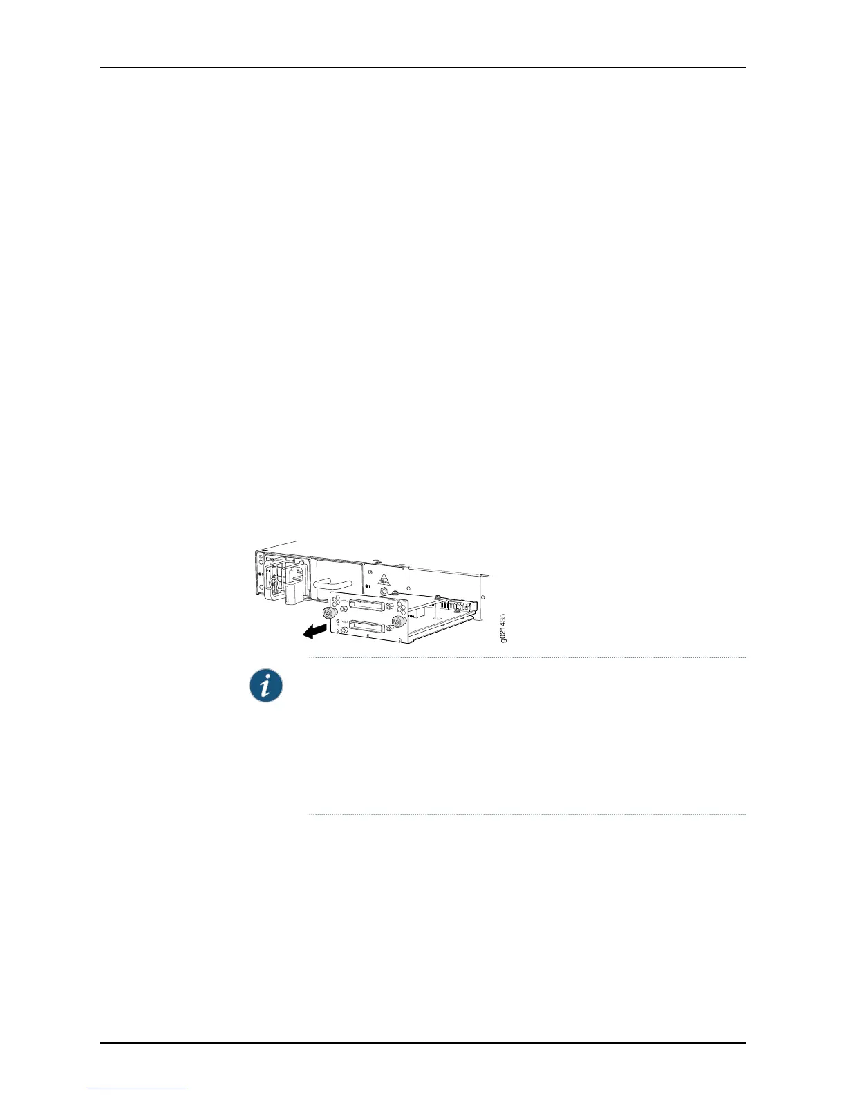
To remove the Virtual Chassis module from the switch (see Figure 71 on page 227):
1. Attach the ESD grounding strap to your bare wrist, and connect the strap to the ESD
point on the chassis.
2. Unscrew both captive screws on the faceplate of the Virtual Chassis module by using
your fingers. If you are unable to unscrew the captive screws by using your fingers, use
the screwdriver.
3. Hold both the captive screws and gently pull the Virtual Chassis module out of the
module slot.
4. Place the Virtual Chassis module in an antistatic bag or on an antistatic mat placed
on a flat, stable surface.
5. If you are not replacing the Virtual Chassis module with an optional module, install
the cover panel over the slot.
Figure 71: Removing the Virtual Chassis Module from an EX4550 Switch
g021435
EX4550-VC1-128G
VCP-1
VCP-0
ST
NOTE: If you have a Juniper J-Care service contract, register any addition,
change, or upgrade of hardware components at
https://www.juniper.net/customers/csc/management/updateinstallbase.jsp .
Failure to do so can result in significant delays if you need replacement parts.
This note applies if you change the type of power supply or add a new type
of expansion module. It does not apply if you replace these components with
the same type of component.
Related
Documentation
• Installing a Virtual Chassis Module in an EX4550 Switch on page 225
• Installing and Removing EX4550 Switch Hardware Components on page 155
• EX4550 Switches Hardware Overview on page 3
227Copyright © 2015, Juniper Networks, Inc.
Chapter 21: Replacing Virtual Chassis Module