To install an expansion module in an EX4550 switch (see Figure 61 on page 210,
Figure 62 on page 211, and Figure 63 on page 211):
1. Attach the ESD grounding strap to your bare wrist, and connect the strap to the ESD
point on the chassis.
If a grounding strap is not available, hold the expansion module in its antistatic bag
in one hand and touch the exposed metallic part of the switch with the other hand to
ground yourself and the component.
2. If the module slot has a cover panel on it, remove the cover panel by using the
screwdriver and save it for later use.
3. Taking care not to touch module components, pins, leads, or solder connections,
remove the expansion module from its bag.
4. Loosen the captive screws on the front faceplate of the expansion module by using
your fingers. If you are unable to loosen the captive screws by using your fingers, use
the screwdriver.
5. Using both hands, place the expansion module in the empty slot and slide it in gently
until it is fully seated.
NOTE: After you have removed an expansion module, wait for at least 5
seconds before you install an expansion module. If you do not wait for at
least 5 seconds, the interfaces on the expansion module might not come
up.
6. Tighten the captive screws by using your fingers or the screwdriver. When the status
(ST) LED turns green, the expansion module is ready for use.
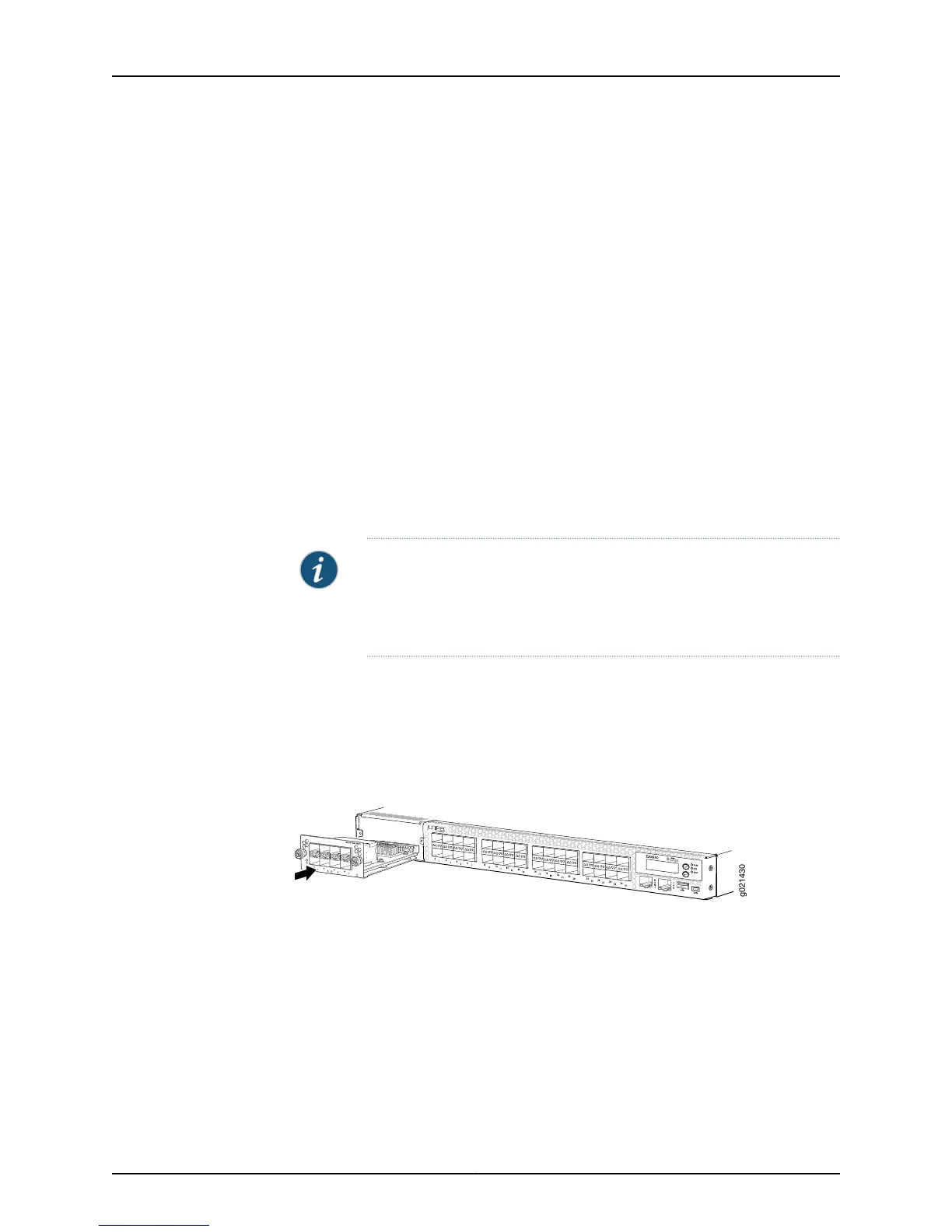
Figure 61 on page 210 shows how to install an SFP+ expansion module on the front panel
of an EX4550-32F switch.
Figure 61: Installing an SFP+ Expansion Module in an EX4550-32F Switch
Figure 62 on page 211 shows how to install a 10GBASE-T expansion module on the front
panel of an EX4550-32T switch.
Copyright © 2015, Juniper Networks, Inc.210
EX4550 Switch Hardware Guide