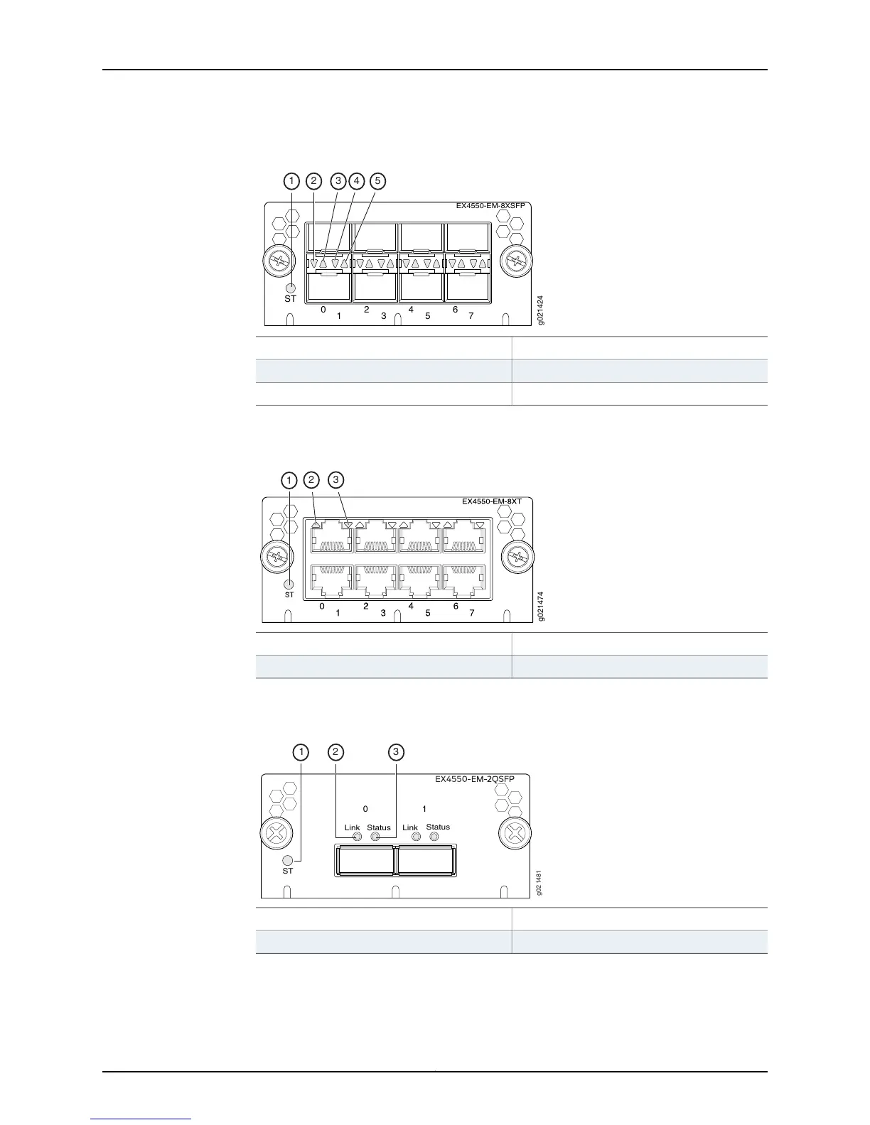
Figure 11: LEDs on an SFP+ Expansion Module
0
ST
2 4 6
1
3 5 7
EX4550-EM-8XSFP
g021424
1
2 3 4 5
4—1— Status lower portStatus LED of the expansion module
5—2— Status upper portLink/Activity lower port
3—Link/Activity upper port
Figure 12 on page 25 shows the location of LEDs on the 10GBASE-T expansion module.
Figure 12: LEDs on a 10GBASE-T Expansion Module
3—1— Link/Activity lower portStatus LED of the expansion module
2—Link/Activity upper port
Figure 13 on page 25 shows the location of LEDs on the QSFP+ expansion module.
Figure 13: LEDs on a QSFP+ Expansion Module
0
1
Link
Status
Link
Status
ST
g02 1481
1
2 3
3—1— Port’s Status LEDStatus LED of the expansion module
2—Port’s Link/Activity LED
Table 9 on page 26 describes the Status LED on the expansion modules.
25Copyright © 2015, Juniper Networks, Inc.
Chapter 2: Chassis Components and Descriptions