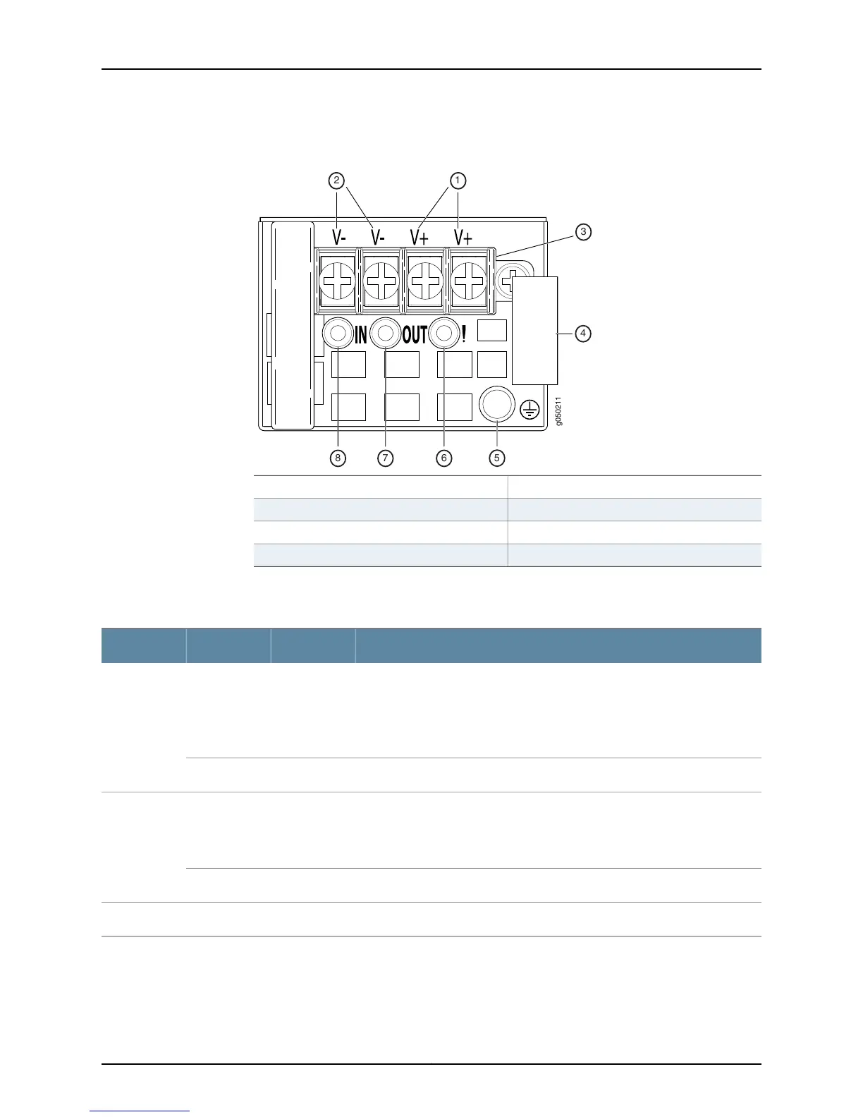
Figure 29: DC Power Supply Faceplate on an EX4550 Switch
5—1— ESD grounding pointV+ input terminals
6—2— ! (Fault) LEDV– input terminals
7—3— OUT (Output) LEDTerminal block
8—4— IN (Input) LEDEjector lever
Table 23 on page 47 describes the LEDs on the DC power supplies.
Table 23: DC Power Supply LEDs on an EX4550 Switch
DescriptionStateColorName
Indicates one of the following:
•
Power supply is disconnected from DC power feed.
•
DC power input voltage is not within normal operating range.
•
No DC power input.
OffUnlitIN
The power supply is receiving power.On steadilyGreen
Indicates one of the following:
•
The power supply is disconnected from the power feed.
•
The power supply is not delivering power correctly.
OffUnlitOUT
The power supply is functioning correctly.On steadilyGreen
The power supply has failed and must be replaced.On steadilyYellow! (Fault)
Related
Documentation
• DC Power Supply in EX4550 Switches on page 44
• DC Power Supply Specifications for EX4550 Switches on page 88
47Copyright © 2015, Juniper Networks, Inc.
Chapter 4: Power Supplies