All the EX4550 switchmodels, except the EX4550-32F-S switches are shipped with three
fan modules pre-installed in the rear panel of the switches. EX4550-32F-S switches are
not shipped with pre-installed fan modules; you must order them separately.
Two variants of fan modules are available, each with a different airflow
direction—back-to-front airflow, indicated by the label AIR IN (AFI) and front-to-back
airflow, indicated by the label AIR OUT (AFO). See “Cooling System and Airflow in an
EX4550 Switch” on page 35.
CAUTION: Do not mix fan modules with different airflow labels (AIR IN (AFI)
and AIR OUT (AFO)) in the same chassis.
Components on the EX4550 Switch
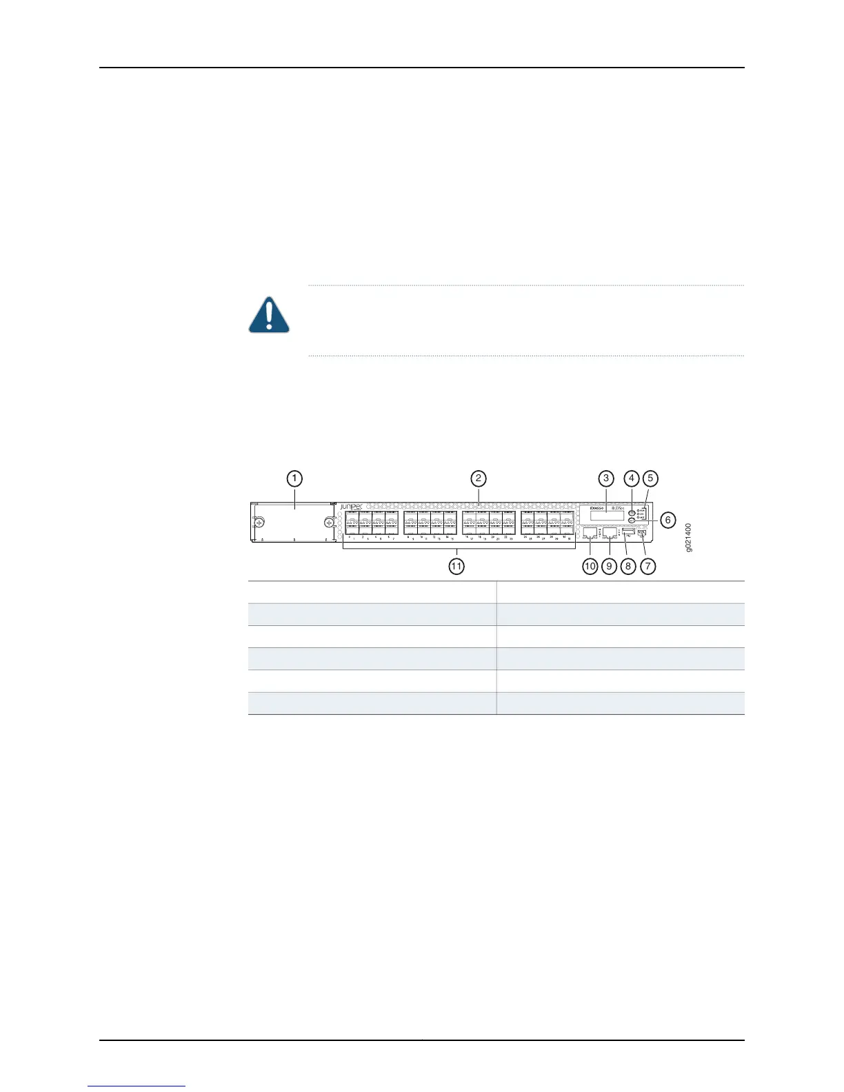
Figure 4 on page 8 shows the components on the front panel of an EX4550-32F switch
(with the module slot cover panel installed).
Figure 4: Components on the Front Panel of an EX4550-32F Switch
7—1— Mini-USB console portModule slot cover panel
8—2— USB portAir vents
9—3— RJ-45 console portLCD panel
10—4— Management portLCD panel Menu button
11—5— SFP+ network portsChassis status LEDs
6—LCD panel Enter button
Figure 5 on page 9 shows the components on the front panel of an EX4550-32T switch
(with the module slot cover panel installed).
Copyright © 2015, Juniper Networks, Inc.8
EX4550 Switch Hardware Guide