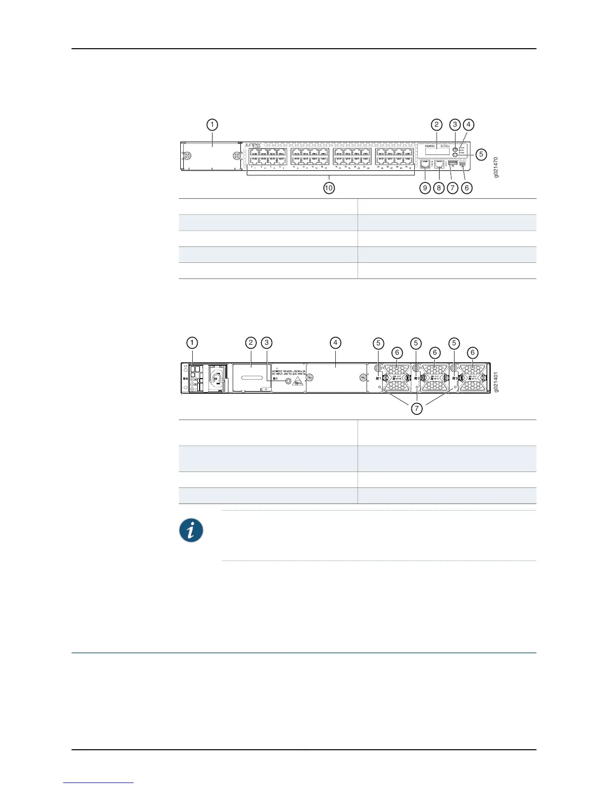
Figure 5: Components on the Front Panel of an EX4550-32T Switch
6—1— Mini-USB console portModule slot cover panel
7—2— USB portLCD panel
8—3— RJ-45 console portLCD panel Menu button
9—4— Management portChassis status LEDs
10—5— Ethernet network portsLCD panel Enter button
Figure 6 on page 9 shows the components on the rear panel of an EX4550 switch (with
the module slot cover panel, an AC power supply, and three fan modules installed).
Figure 6: Components on the Rear Panel of an EX4550 Switch
5—1— Fan module slot labelsAn AC power supply (in power supply slot
0)
6—2— Fan modulesPower supply cover panel (in power supply
slot 1)
7—3— Fan status LEDsESD point
4—Module slot cover panel
NOTE: The protective earthing terminal is located on the left side of the
chassis. See “Connecting Earth Ground to an EX Series Switch” on page 157.
Related
Documentation
EX4550 Switch Models on page 9•
• Field-Replaceable Units in EX4550 Switches on page 18
• EX Series Virtual Chassis Overview
EX4550 Switch Models
Table 4 on page 10 lists the available EX4550 switches.
9Copyright © 2015, Juniper Networks, Inc.
Chapter 1: System Overview