an EX Series Switch” on page 157. An EX4550 switch gains additional
grounding when you plug the power supply in the switch into a grounded
AC power outlet by using the AC power cord appropriate for your
geographical location (see “AC Power Cord Specifications for an EX4550
Switch” on page 86).
•
Install the power supply in the chassis. For instructions on installing a power supply in
an EX4550 switch, see “Installing an AC PowerSupply in an EX4550 Switch” on page 203.
NOTE: Each power supply must be connected to a dedicated power source
outlet.
To connect AC power to an EX4550 switch:
1. Attach the grounding strap to your bare wrist and to a site ESD point.
2. Ensure that the power supplies are fully inserted in the chassis and the latches are
secure. If only one power supply is installed, ensure thata blank cover panel is installed
over the second power supply slot.
3. Locate the power cord or cords shipped with the switch; the cords have plugs
appropriate for your geographical location. See “AC Power Cord Specifications for an
EX4550 Switch” on page 86.
WARNING: Ensure that the power cord does not block access to switch
components or drape where people can trip on it.
4. Insert the coupler end of the power cord into the AC power cord inlet on the AC power
supply faceplate.
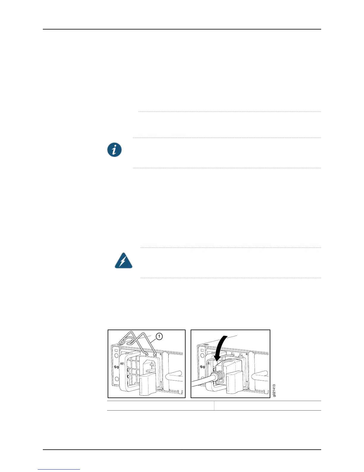
5. Push the power cord retainer onto the power cord (see Figure 44 on page 164).
Figure 44: Connecting an AC Power Cord to an AC Power Supply in an
EX4550 Switch
1— Power cord retainer clip
6. If the AC power source outlet has a power switch, set it to the off (O) position.
Copyright © 2015, Juniper Networks, Inc.164
EX4550 Switch Hardware Guide