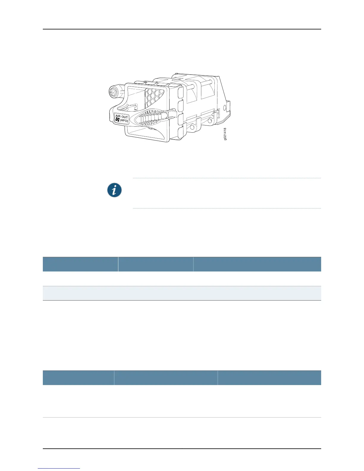
Figure 21: Fan Module Used in an EX4550 Switch
You remove and replace a fan module from the rear panel of the chassis. The switch
continues to operate for a limited period of time (30 seconds) during the replacement
of the fan module without thermal shutdown.
NOTE: All three fan modules must be installed for optimal functioning of the
switch.
Two variants of fan modules are available, each with a different airflow
direction—back-to-front airflow, indicated by the label AIR IN (AFI), or front-to-back,
indicated by the label AIR OUT (AFO). Table 17 on page 36 lists the available fan module
model numbers and the direction of airflow in them.
Table 17: Fan Modules in EX4550 Switches
Direction of Airflow in the Fan ModuleLabel on the Fan ModuleModel Number
Back-to-front—air comes in from the back of the switch.AIR IN (AFI)EX4550-FAN-AFI
Front-to-back—air exhausts from the back of the switch.AIR OUT (AFO)EX4550-FAN-AFO
Airflow Direction in EX4550 Switches
Table 18 on page 36 shows the direction of airflow in EX4550 switches as shipped. All
the EX4550 switches except the EX4550-32F-S switches have the fan modules and
power supplies preinstalled on the rear panel of the switches. Power supplies and fan
modules for the EX4550-32F-S switch are not shipped by default; you must order them
separately.
Table 18: Airflow Direction in EX4550 Switches
Direction of AirflowFan Modules and Power SupplyModel Number
Back-to-front—air intake to cool the chassis
is through the vents on the rear panel of the
chassis, and hot air exhausts through the
vents on the front panel of the chassis.
The switch ships with three fan modules, each
bearing a label AIR IN (AFI), and an AC power
supply bearing a label AFI.
•
EX4550-32F-AFI
•
EX4550–32T-AFI
Copyright © 2015, Juniper Networks, Inc.36
EX4550 Switch Hardware Guide