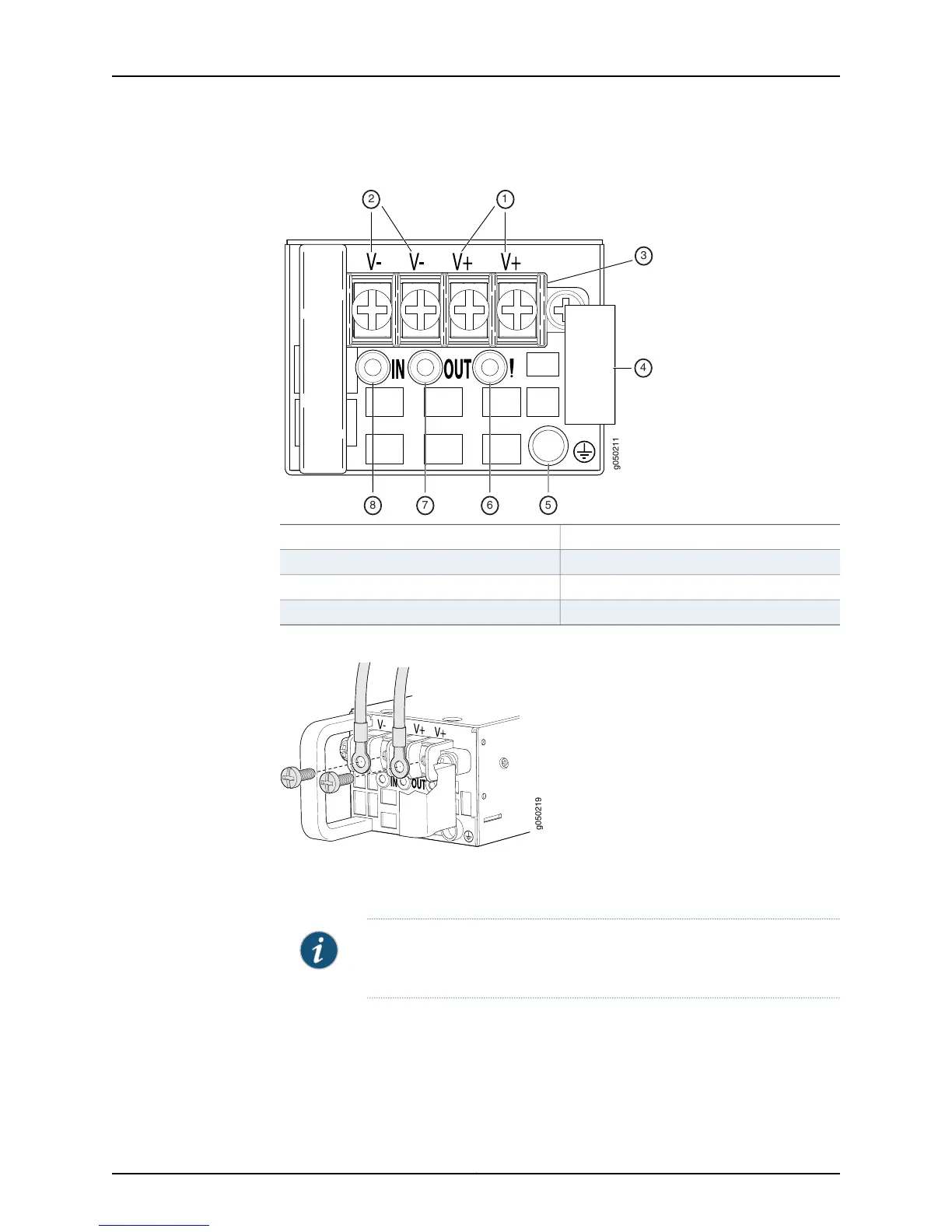
Figure 45: DC Power Supply Faceplate for an EX4550 Switch
5—1— ESD grounding pointV+ input terminals
6—2— Fault LEDV– input terminals
7—3— Output LEDTerminal block
8—4— Input LEDEjector lever
Figure 46: Securing Ring Lugs to the Terminals on the DC Power Supply
8. Replace the terminal block cover.
9. Close the input circuit breaker.
NOTE: The device powers on as soon as power is provided to the power
supply. There is no power switch on the device.
10. Verify that the IN and OUT LEDs on the power supply are lit green and are on steadily.
Related
Documentation
• DC Power Supply in EX4550 Switches on page 44
• DC Power Supply LEDs in EX4550 Switches on page 46
Copyright © 2015, Juniper Networks, Inc.168
EX4550 Switch Hardware Guide