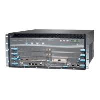
The following sample configuration shows an SRX5400 Services Gateway chassis with various power
supplies and:
•
Two SRX5K-SPC-4-15-320 (SPC2) Services Processing Card (SPC) (slots 1 and 2)
•
One IOC3 (SRX5K-MPC3-40G10G or SRX5K-MPC3-100G10G) (slot 1/0)
•
One switch control board SRX5K-SCB3 (SCB3) and one Routing Engine RE2 installed in SCB slot 0
1. Calculate the power requirements (usage) as shown in Table 38 on page 158.
Table 38: Sample Power Requirements for an SRX5400 Services Gateway with SCB3, IOC3, and RE2
Power RequirementPart NumberChassis Component
40 WSRX5400-CHASBase system
75 WSRX5400-FANFan tray
607 WIOC3MPC - slot 1/0
585 W * 2 = 1170 WSCP2SPC - slots 1 and 2
300 W
90 W
SCB3
RE2
SCB 0
2282 WTotal power requirement
2207 WTotal power requirement excluding cooling system
2. Evaluate the power budget. In this step, we check the required power against the maximum output
power of available power supply options.
NOTE: The power for the cooling system comes from a different tap on the power supply,
reserved for the cooling system only. The cooling system power requirement does not
need to be deducted from the output power budget of the power supply.
Table 39 on page 159 lists the power supplies, their maximum output power, and unused power (or a
power deficit) for an AC-powered services gateway. Table 40 on page 159 lists the power supplies, their
maximum output power, and unused power (or a power deficit) for an AC-powered services gateway.
158

 Loading...