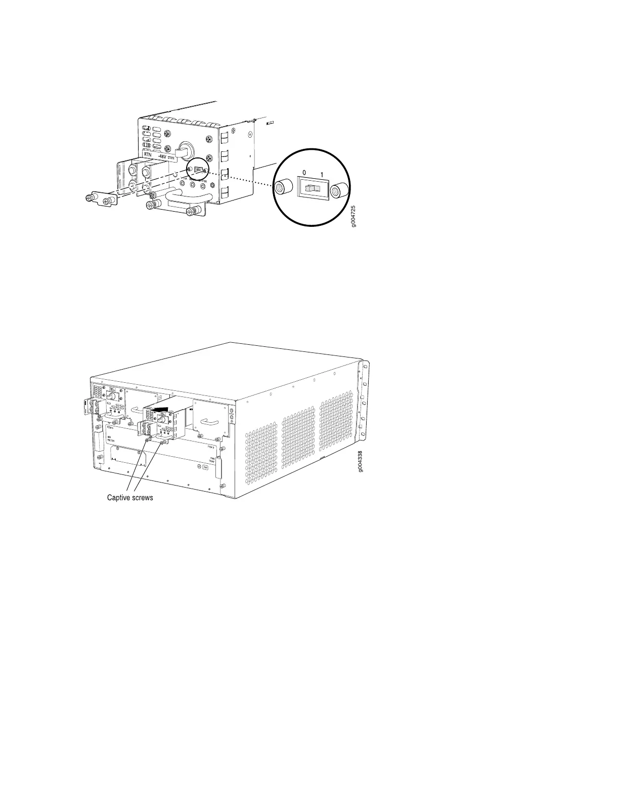
Figure 102: DC Power Supply Input Mode Switch
5. Using both hands, slide the power supply straight into the chassis until the power supply is fully seated
in the chassis slot. The power supply faceplate should be flush with any adjacent power supply faceplate
(see Figure 103 on page 240).
Figure 103: Installing a DC Power Supply
6. Tighten the captive screws on the lower edge of the power supply faceplate.
7. Remove the clear plastic cover protecting the terminal studs on the faceplate.
8. Remove the nuts and washers from the terminal studs.
9. Secure each power cable lug to the terminal studs, first with the washer, then with the nut. Apply
between 23 lb-in. (2.6 Nm) and 25 lb-in. (2.8 Nm) of torque to each nut. (see Figure 104 on page 241).
a. Attach the positive (+) DC source power cable lug to the RTN (return) terminal.
b. Attach the negative (–) DC source power cable lug to the –48V (input) terminal.
240

 Loading...


