interface, the alarm relay contacts are also activated. The alarm relay contacts are located on the upper
right of the craft interface.
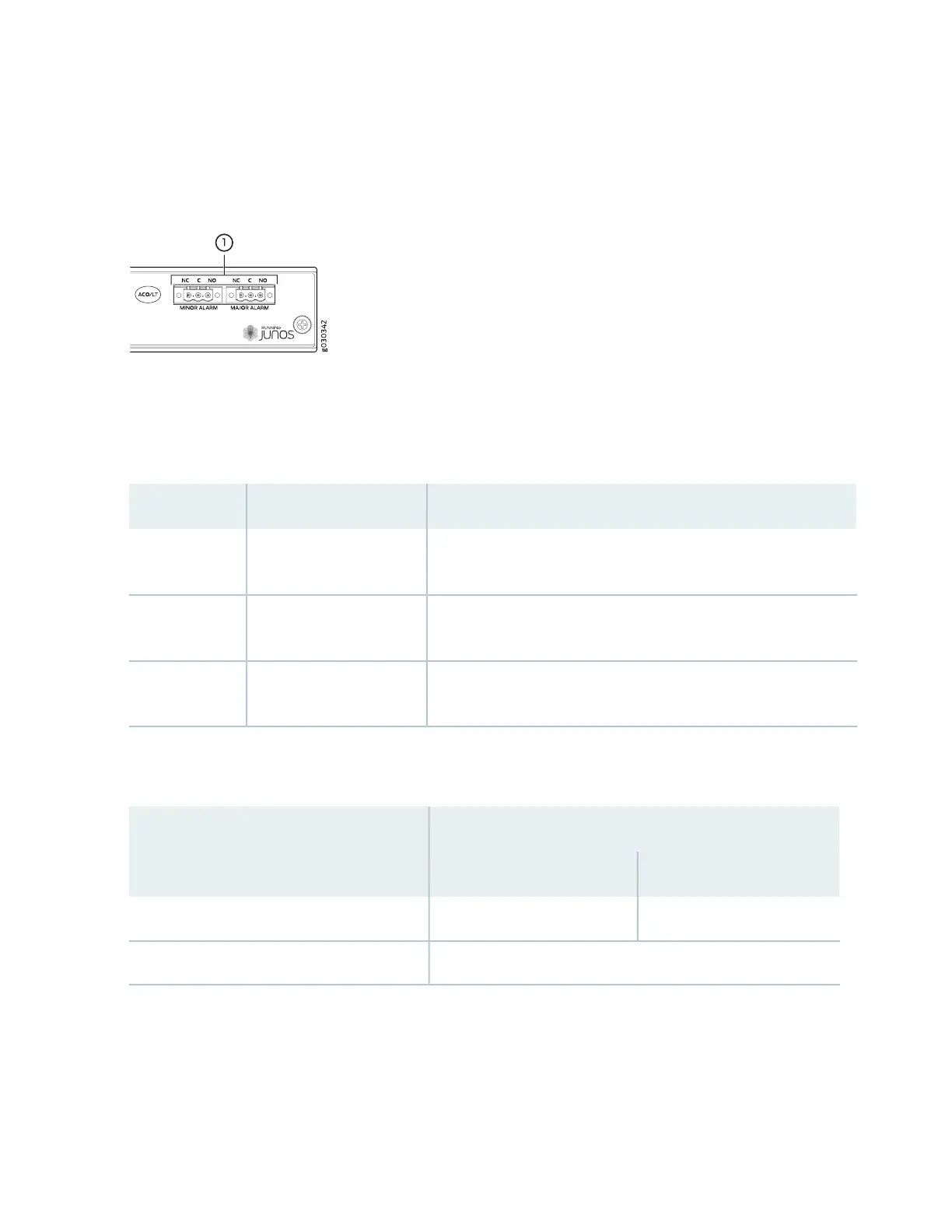
Figure 5: Alarm Relay Contacts
The alarm relay contacts consist of two sets of connectors, one set for each of the two alarms (major and
minor). For each alarm color there are three connectors. Table 11 on page 40 describes the functions of
the connectors.
Table 11: Alarm Relay Contact Functions
FunctionContact NameContact Label
Connects the alarm relay to an external alarm-reporting device that
activates when the circuit between C and NC is closed.
Normally ClosedNC
Connects the alarm relay to the current source for the external
alarm-reporting device.
Current InC
Connects the alarm relay to an external alarm-reporting device that
activates when the circuit between C and NC is open.
Normally OpenNO
Table 12 on page 40 shows the electrical specifications for the alarm relay contacts.
Table 12: Alarm Relay Contact Electrical Specifications
Current Type
DCAC
30250Maximum Voltage
8 AMaximum Current
Figure 6 on page 41 shows an example wiring diagram for a simple alarm reporting device. In this case the
device is a 12-volt light bulb that illuminates when the device encounters a condition that activates the
major alarm LED and relay contacts. The alarm relay contacts can also be used to activate other devices
such as bells or buzzers.
40

 Loading...


