Section 3: Functions and features Series 2280 Precision DC Power Supply Reference Manual
3-22 077085503 / March 2019
Do not apply more than 50 mA (maximum current) or exceed +33 V (maximum voltage) on the
digital I/O port. Applying current or voltage exceeding these limits may damage the
instrument.
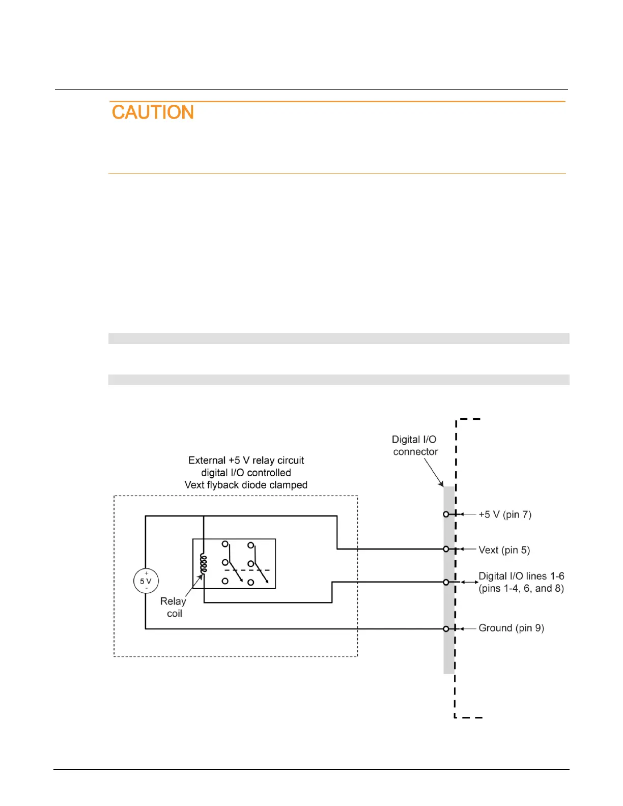
Refer to the following figure for a simplified schematic of a sample control circuit for a relay. You can
externally power a different device by replacing the relay coil with the other device. When using the
V
ext
pin to control externally powered devices, make sure to configure the corresponding digital output
lines. In the low state (0 V), the output transistor sinks current through the external device. In the high
state, the output transistor is off (transistor switch is open). This interrupts current flow through the
external device. This type of application typically uses an active-low signal (set the bit to 0) to turn the
relay on (ON = 0 V).
For example, if you configure line 4 as the digital output line, you can send the following command to
sink relay current:
:DIG:LINE4:FUNC:MOUTL
To stop relay current, sent the following command
:DIG:LINE4:FUNC:MOUTH
Figure 64: Digital I/O Vext (example external circuit)

 Loading...


