Appendix B: Verification Series 2280 Precision DC Power Supply Reference Manual
B-20 077085503 / March 2019
7. Set the DUT to the full-scale output current.
8. Set the DUT to 0% of the full-scale output voltage (0 V).
9. Turn the DUT output on.
10. Enter the voltmeter reading in the DC voltage setting accuracy with remote sense (on page B-3)
and the DC voltage readback accuracy with remote sense (on page B-5) tables.
11. Enter the DUT readback voltage in the DC voltage readback accuracy with remote sense (on
page B-5) table.
12. Calculate the difference of the two measurements taken in step 10 and step 11 and enter the
absolute value in the difference column of the DC voltage readback accuracy with remote sense
(on page B-5) table.
13. Increase the DUT output voltage by 25% of the full-scale output voltage.
14. Repeat step 10 and step 11 until you complete testing at 100% of the full-scale output voltage.
15. Power off the DUT.
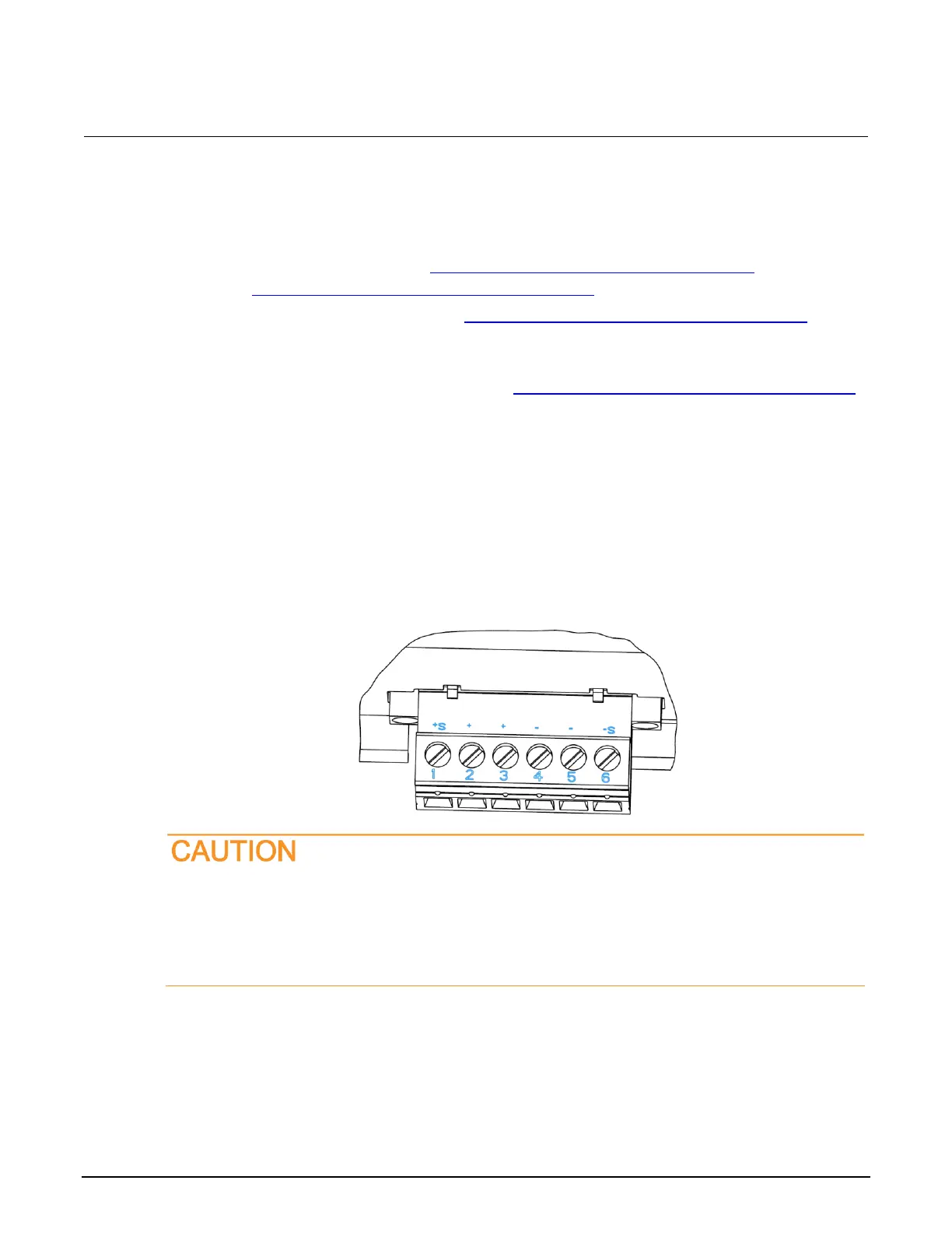
16. Disconnect the wires from the remote sense connector and reinstall the shorting jumpers
between the output terminals and sense terminals, as shown in the following figure. One jumper
goes in terminals 1 and 2 and the other goes in terminals 5 and 6.
Figure 102: Connector terminals
The jumper cables must be installed if you are going to use 2-wire connections.
Even if you are using the front-panel connectors, the output mating connector (with jumper
wires installed) must be connected to the Series 2280 rear-panel output connector to ensure
proper instrument performance.
17. Power on the DUT.

 Loading...


