Series 2280 Precision DC Power Supply Reference Manual Appendix B: Verification
077085503 / March 2019 B-27
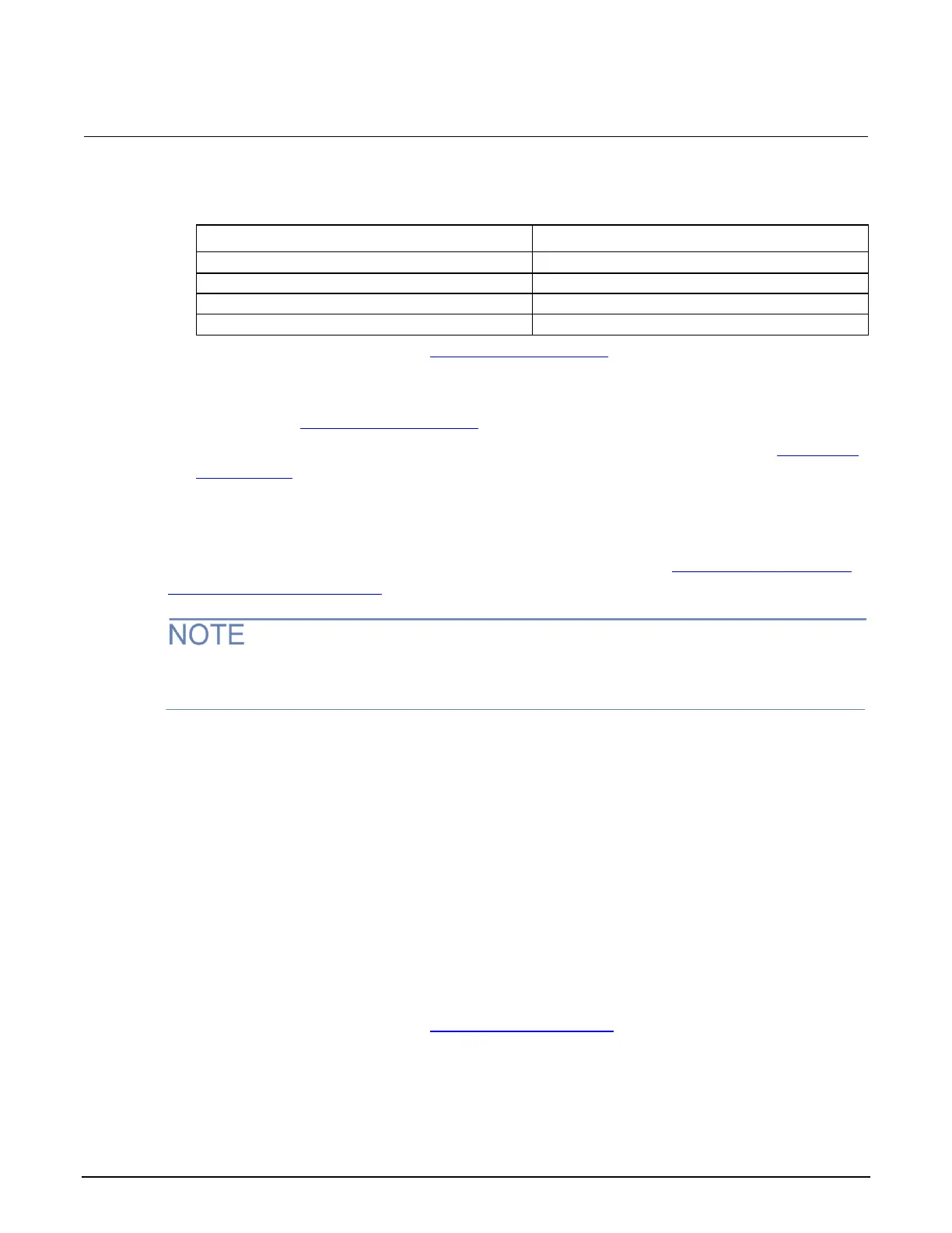
10. Change the AC power source output to match the Voltage Selector switch setting of the DUT, as
shown in the following table.
DUT voltage selector switch
11. Enter the voltmeter reading in the DC voltage line regulation (on page B-7) table under the Nom
column for your product.
12. Calculate the two values: Nom – Min and Max – Nom. Enter the values in the appropriate
columns in the DC voltage line regulation (on page B-7) table.
13. Enter the largest of the two values calculated in step 13 in the Largest column in the DC voltage
line regulation (on page B-7) table.
Check DC voltage load regulation
This procedure uses the same test setup as the previous procedure (see Check DC voltage setting
accuracy without remote sense (on page B-21)).
Make sure the warm-up criteria have been met, as described in the Performance verification
conditions.
To check DC voltage load regulation:
1. Set the voltmeter as follows:
Set to measure DC voltage.
Set the current range to autorange.
Verify that the Math mx + b function is disabled, assuring that voltage is being read.
2. Set the electronic load as follows:
Set to constant current (CC) mode.
Set to draw 0 A.
3. Set the device under test (DUT) to 100% of the full-scale output current.
4. Set the DUT to 100% of the full-scale output voltage.
5. Turn the DUT output on.
6. Enter the voltmeter reading in the DC voltage load regulation (on page B-7) table under the
Minimum column for your product.

 Loading...


