-486 Keysight E4980A/AL User’s Guide
Handler Interface
Setting Up the Handler Interface Board
-
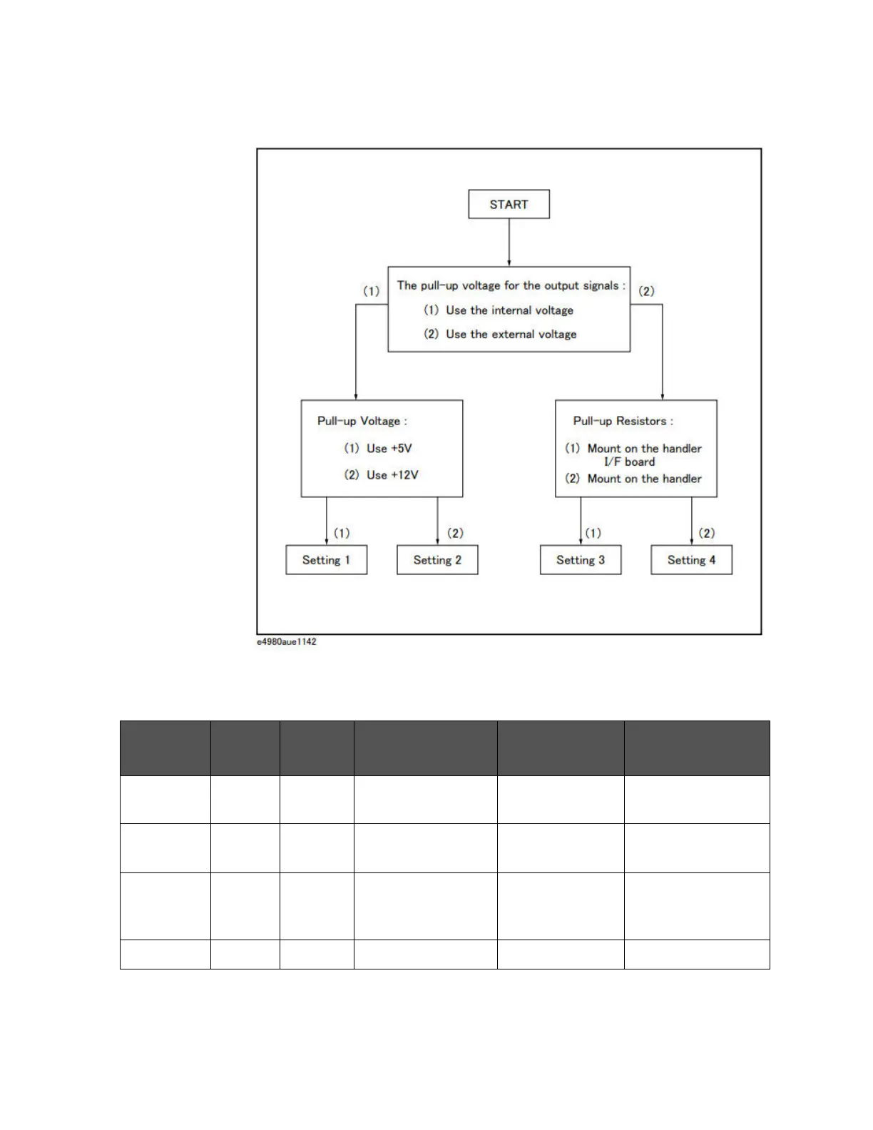
Figure E-9 Flow chart for determining the jumper and bit switch settings
Step 6. Set up the jumpers as instructed in
Table E-11.
Table E-11 Jumper and bit switch settings for test result output signals
Setting # JP1 Bit 5 of
S1
Circuit common Pull-up resistor
mounting
Pull-up voltage
Setting 1 1 On Instrument’s circuit
common
Required +5 V, internal
Setting 2 2 On Instrument’s circuit
common
Required +12 V, internal
Setting 3 3 Off COM1 Required +5 V through +24 V,
external
(EXT.DCV1)
Setting 4 - Off COM1 Not required -