-488 Keysight E4980A/AL User’s Guide
Handler Interface
Setting Up the Handler Interface Board
-
where:
— Vp [V]: pull-up voltage
— R [k]: pull-up resistance
For the typical pull-up resistor values, refer to Table E-14 on page 488.
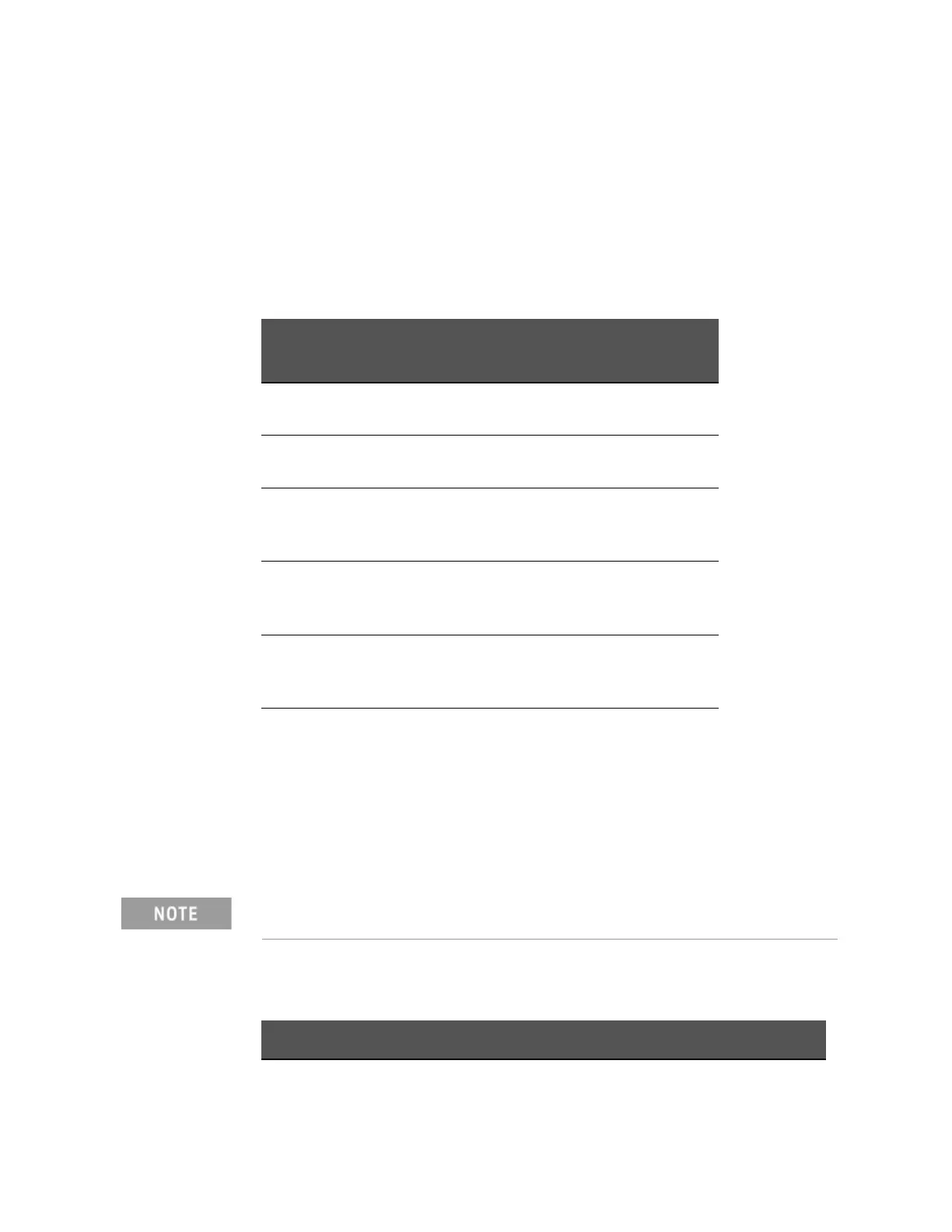
Step 11. Set up the bit switch for input signals as instructed in Table E-13.
Step 12. Connect the flat cable to the handler interface board. Reinstall the handler
interface board to its original position and secure it with the two screws.
The typical pull-up resistor values are:
Table E-13 Bit switch settings for input signals
Drive voltage Bits 1 through 4 of
S1
1
1. Only one of bits 1 through 4 of the bit switch can be ON at a time.
Circuit common
+5 V, internal Turn ON bit 1. Instrument’s circuit
common
+12 V, internal Turn ON bit 3. Instrument’s circuit
common
+5 V through +6 V,
external
(EXT.DCV2)
Turn ON bit 1. COM2
+6 V through +9 V,
external
(EXT.DCV2)
Turn ON bit 2. COM2
+9 V through +15 V,
external
(EXT.DCV2)
Turn ON bit 3. COM2
+15 V through +24 V,
external
(EXT.DCV2)
Turn ON bit 4. COM2
When tightening each screw, take care not to apply excessive force
because doing so can break the tapped hole. (0.98 N-Em, 0.1 kgf-m Max).
Table E-14 The typical pull-up resistor vaules
Pull-Up Voltage Pull-Up Resistor Keysight Part Number
5 V 1.7 k ( = 5 V / 3 mA) 1810-0276 (1.5 k)