116 Keysight InfiniiVision HD3-Series Oscilloscopes User's Guide
7 Digital Channels
Sharing one probe ground with many probes forces all the current that flows into
each probe to return through the same common ground inductance of the probe
whose ground return is used. The result is increased current (di) in the above
equation, and, depending on the transition time (dt), the common mode voltage
may increase to a level that causes false data generation.
In addition to the common mode voltage, longer ground returns also degrade the
pulse fidelity of the probe system. Rise time is increased, and ringing, due to the
undamped LC circuit at the input of the probe, is also increased. Because the
digital channels display reconstructed waveforms, they do not show ringing and
perturbations. You will not find ground problems through examination of the
waveform display. In fact, it is likely you will discover the problem through random
glitches or inconsistent data measurements. Use the analog channels to view
ringing and perturbations.
Best Probing Practices
Because of the variables L, di, and dt, you may be unsure how much margin is
available in your measurement setup. The following are guidelines for good
probing practices:
• The ground lead from each digital channel group (D15–D8 and D7–D0) should
be attached to the ground of the device under test if any channel within the
group is being used for data capture.
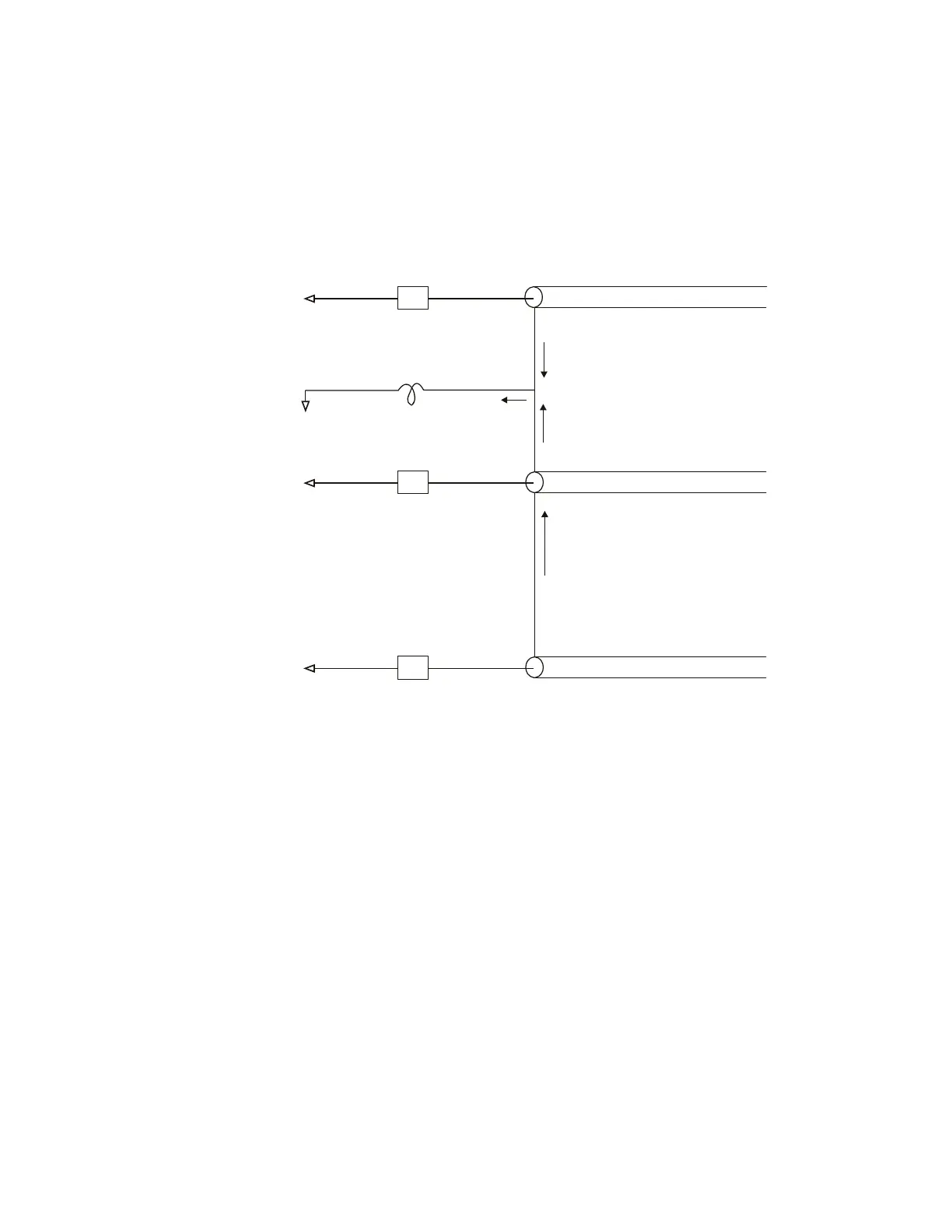
Figure 23 Common Mode Input Voltage Model
Z
in
Z
in
i
n
i
2
+i
2
i
1
i
1
+i
n
+i
n
Z
in
Probe 1
Probe
Ground
Probe 2
Probe N
L (GND)
Vn (Common Mode)
 Loading...