Getting Started 1
Keysight InfiniiVision HD3-Series Oscilloscopes User's Guide 21
Learn the Front Panel Inputs and Outputs
Horizontal
Trigger
Level
Markers
Vertical
1 GHz 14 bit
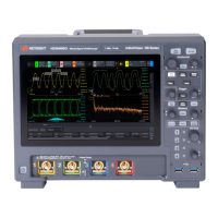
Mixed Signal OscilloscopeHD304MSO
InfiniiVision HD-Series
Probe Comp
4
3
21
3
4
Digital
Protocol
Decode
Markers
Wave
Gen
Touch
Auto
Scale
Zoom
Single
Run
Stop
Save
Screen
Clear
Display
Default
Setup
Save
Screen
Slope
Force
Mode
Measure
3. Probe Comp
and Ground
terminals
2. Analog
channel
inputs
4. USB
Host
ports
1. Power switch
1. Power switch Press once to switch power on; press again to switch power off.
The front panel switch is a standby switch only and is not a LINE switch. The detachable
power cord is the instrument disconnecting device. It disconnects the mains circuits from the
mains supply before other parts of the instrument. Therefore, install the instrument so that
the detachable power cord is readily identifiable and is easily reached by the operator.
See "Power-On the Oscilloscope" on page 25.
2. Analog channel
inputs
Attach oscilloscope probes or BNC cables to these BNC connectors.
With the InfiniiVision HD3-Series oscilloscopes, you can set the input impedance of the
analog channels to either 50 Ω or 1 MΩ. See
"To specify channel input impedance" on
page 58.
The InfiniiVision HD3-Series oscilloscopes also provide the AutoProbe interface. The
AutoProbe interface uses a series of contacts directly below the channel's BNC connector to
transfer information between the oscilloscope and the probe. When you connect a
compatible probe to the oscilloscope, the AutoProbe interface determines the type of probe
and sets the oscilloscope's parameters (units, offset, attenuation, coupling, and impedance)
accordingly.
 Loading...


