140 Keysight InfiniiVision HD3-Series Oscilloscopes User's Guide
10 Triggers
• For analog channel sources, use Trigger Level field to enter the value.
• For digital channel sources, use the Logic dop-down list to select the
threshold level.
The value of the trigger level or digital threshold is displayed in the upper-right
corner of the display.
5 Use the Slope drop-down list to select positive ( ) or negative ( ) polarity for
the pulse width you want to capture.
The selected pulse polarity is displayed in the trigger badge. A positive pulse is
higher than the current trigger level or threshold and a negative pulse is lower
than the current trigger level or threshold.
When triggering on a positive pulse, the trigger will occur on the high to low
transition of the pulse if the qualifying condition is true. When triggering on a
negative pulse, the trigger will occur on the low to high transition of the pulse if
the qualifying condition is true.
6 Use the Qualifier drop-down list to select the time qualifier:
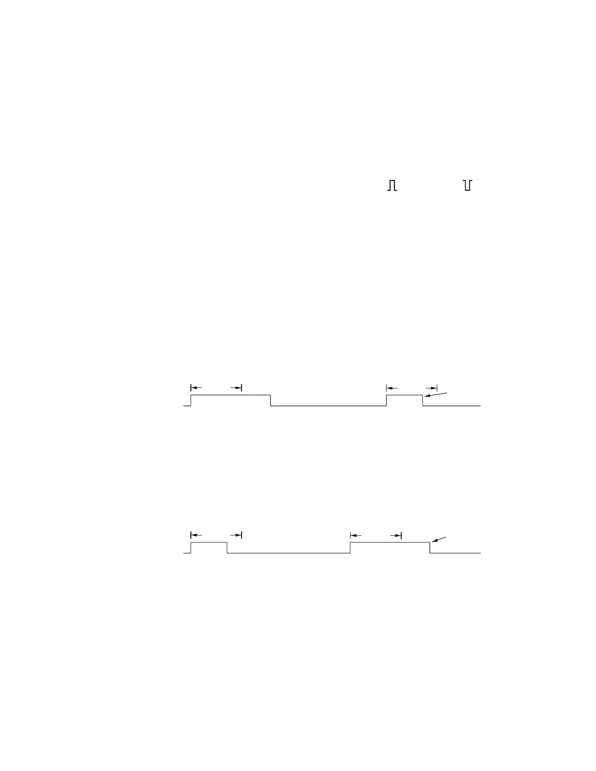
• Less than a time value (<).
For example, for a positive pulse, if you set t<10 ns:
Use the < (Less than) field to enter the pulse width qualifier time.
The time value can be from 2 ns to 10 s (5 ns to 10 s for 350 MHz and lower
bandwidth models).
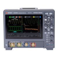
• Greater than a time value (>).
For example, for a positive pulse, if you set t>10 ns:
Use the > (Gre ater than) field to enter the pulse width qualifier time.
The time value can be from 2 ns to 10 s (5 ns to 10 s for 350 MHz and lower
bandwidth models).
• Within a range of time values (><).
For example, for a positive pulse, if you set t>10 ns and t<15 ns:
 Loading...


