SPI Triggering and Protocol Decode 28
Keysight InfiniiVision HD3-Series Oscilloscopes User's Guide 349
• Enter the MISO signal threshold voltage level.
The threshold voltage level is used in decoding, and it will become the
trigger level when the trigger type is set to the selected serial decode slot.
• Select the number of bits to ignore (delay) before decoding the MISO
stream.
• Frame by — Select a framing signal that the oscilloscope will use for determining
which clock edge is the first clock edge in the serial stream.
You can set the oscilloscope to trigger during a high chip select (CS), a low chip
select (~CS), or after a Timeout period during which the clock signal has been
idle.
• If the framing signal is set to CS (or ~CS), the first clock edge as defined,
rising or falling, seen after the CS (or ~CS) signal transitions from low to high
(or high to low) is the first clock in the serial stream.
CS or ~CS — Select the channel that is connected to the SPI frame line.
The label (~CS or CS) for the source channel is automatically set. The data
pattern and the clock transition must occur during the time when the
framing signal is valid. The framing signal must be valid for the entire data
pattern.
Threshold — Enter the chip select signal threshold voltage level.
The threshold voltage level is used in decoding, and it will become the
trigger level when the trigger type is set to the selected serial decode slot.
• If the framing signal is set to Timeout, the oscilloscope generates it's own
internal framing signal after it sees inactivity on the serial clock line.
Timeout — Set the minimum time that the Clock signal must be idle (not
transitioning) before the oscilloscope will search for the Data pattern on
which to trigger.
The Timeout value can be set anywhere from 100 ns to 10 s.
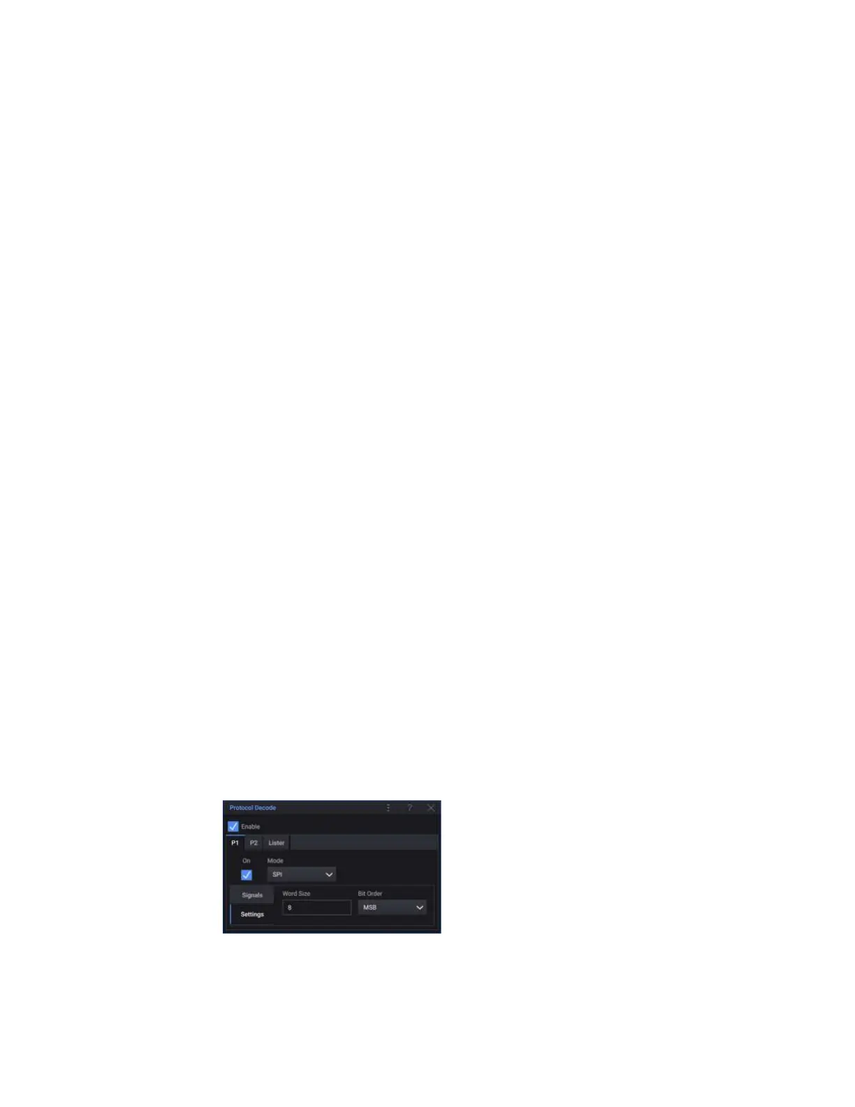
Settings The SPI protocol decode mode has these controls for decode settings:
• Word Size — Enter the number of bits in a word.
 Loading...


