AKD Installation | 9 Electrical Installation
9.9 DC Bus link (X3, X14)
The DC bus link can be connected in parallel so that the regen power is divided between all
the drives that are connected to the same DC bus link circuit. Every drive must have it's own
power connection to mains voltage, even if the DC bus link is used. Drives working gen-
eratively very often should be placed beside drives, which need energy. That reduces current
flow on longer distances. For fuse type definition refer to (➜ # 40).
The sum of the rated currents for all of the drives connected in parallel to an AKD-x003 to
024 must not exceed 48A.
Use 6mm², unshielded single cores with a max. length of 200mm; use 6mm² shielded
cables for longer lengths. In this case no fuse for line protection is required.
The sum of the rated currents for all of the AKD-x048 connected in parallel to an AKD-
x048 must not exceed 96A. AKD-x048 should be connected in parallel only with AKD-
x048 drives. Use 16mm², unshielded single cores with a max. length of 30mm; use
16mm² shielded cables for longer lengths.
The drives can be destroyed, if DC bus link voltages are different. Only drives with mains
supply from the same mains (identical mains supply voltage) may be connected by the DC
bus link. DC bus link connection of AKD-x048 to other drives than AKD-x048 is not allowed.
The phase lost/ main control is not working on DC-Bus connected drives. A phase lost on a
drive inside a DC Bus connection will be not detected. External phase monitoring to prevent
overload of the rectifier is recommended.
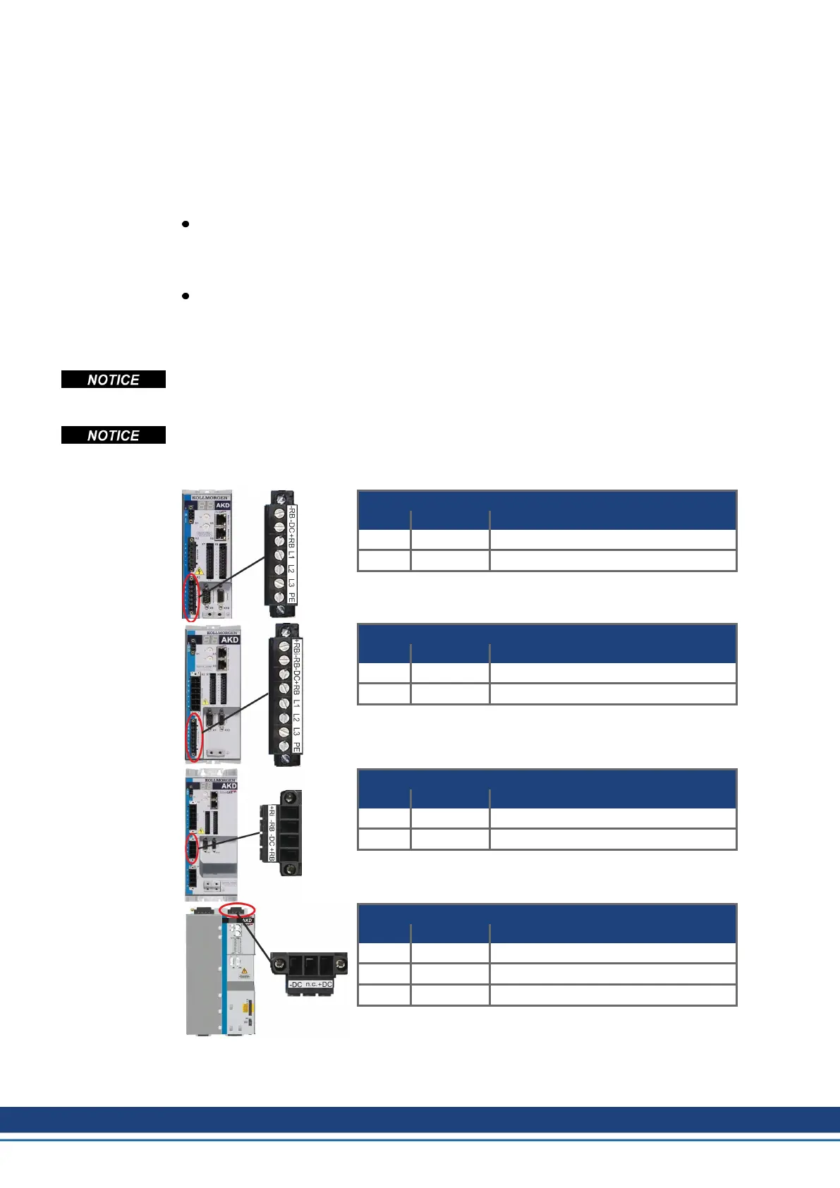
AKD-x00306 to AKD-x00606 (X3)
Pin Signal Description
2 -DC DC-Link Bus negative
3 +DC (+RB) DC-Link Bus positive
AKD-x01206 (X3)
Pin Signal Description
3 -DC DC-Link Bus negative
4 +DC (+RB) DC-Link Bus positive
AKD-x02406 & AKD00307 to AKD02407 (X3)
Pin Signal Description
3 -DC DC-Link Bus negative
4 +DC (+RB) DC-Link Bus positive
AKD-x04807 (X14)
Pin Signal Description
1 -DC DC-Link Bus negative
2 n.c. not connected
3 +DC DC-Link Bus positive
NOTE: Should be connected in parallel only with AKD-x048
drives.
108 Kollmorgen | kdn.kollmorgen.com | October 2017

 Loading...


