EasyManuals Logo

Kollmorgen AKD series Installation Manual

Kollmorgen AKD series
216 pages
To Next Page IconTo Next Page
To Previous Page IconTo Previous Page
Page #140 background imageLoading...
Page #140 background image
AKD Installation | 9 Electrical Installation
9.13.2 Command encoder signal connection
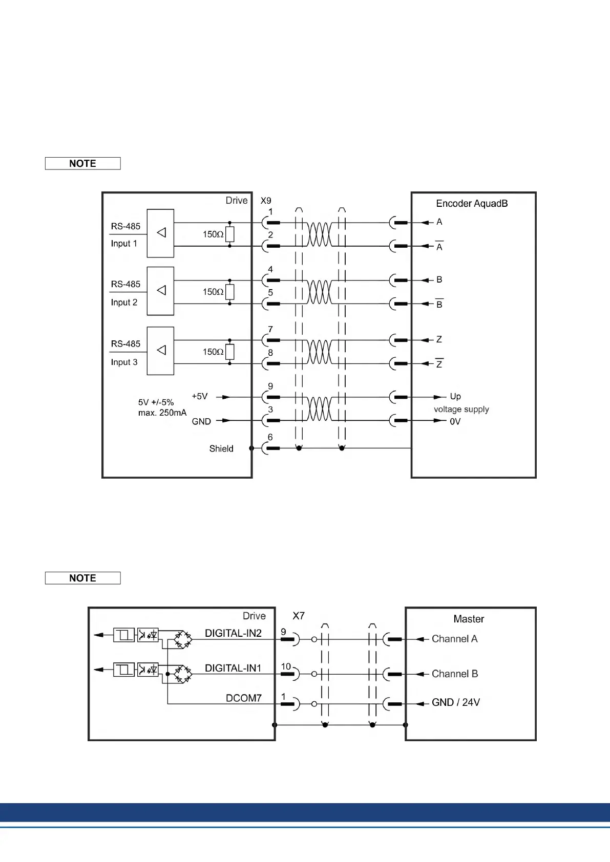
9.13.2.1 Incremental encoder input 5 V (X9)
A 5 V A quad B encoder, or the encoder emulation output of another drive can be connected
to this input and used as a commander encoder, dual loop feedback, gearing or camming
input. Parameter setting FB2.MODE = 0, FB2.SOURCE=1.
Don't use for primary motor feedback connection!
Connection Diagram
9.13.2.2 Incremental encoder input 24 V (X7)
A 24 V A quad B encoder can be connected to the digital inputs 1 and 2 and used as a com-
mander encoder, dual loop feedback, gearing or camming input.
Parameter setting FB2.MODE = 0, FB2.SOURCE=2.
Don't use for primary motor feedback connection!
Connection Diagram
140 Kollmorgen | kdn.kollmorgen.com | October 2017

Table of Contents

Other manuals for Kollmorgen AKD series

Questions and Answers:

Question and Answer IconNeed help?

Do you have a question about the Kollmorgen AKD series and is the answer not in the manual?

Kollmorgen AKD series Specifications

General IconGeneral
Continuous CurrentUp to 180 A
Control ModesPosition, Velocity, Torque
Communication InterfacesEtherCAT, CANopen, Modbus TCP/IP
Feedback OptionsResolver, Encoder
Safety FeaturesSafe Torque Off (STO), Safe Stop 1 (SS1)
Protection FeaturesOvervoltage, Undervoltage, Overcurrent, Short Circuit, Overtemperature
Switching Frequency8 kHz, 16 kHz
Ambient Temperature0°C to 40°C
Operating Temperature0 - 40 °C (derating may apply)
Humidity5% to 95% non-condensing

Related product manuals