9.13.1.2 Connector X9 Input
Technical characteristics
Electrical interface: RS-485
Maximum signal input frequency: 3MHz
Input signal voltage range: +12 V to -7 V
Supply voltage (only applicable to Incremental Encoder Input): +5 V ±5%
Maximumsupply current: 250 mA
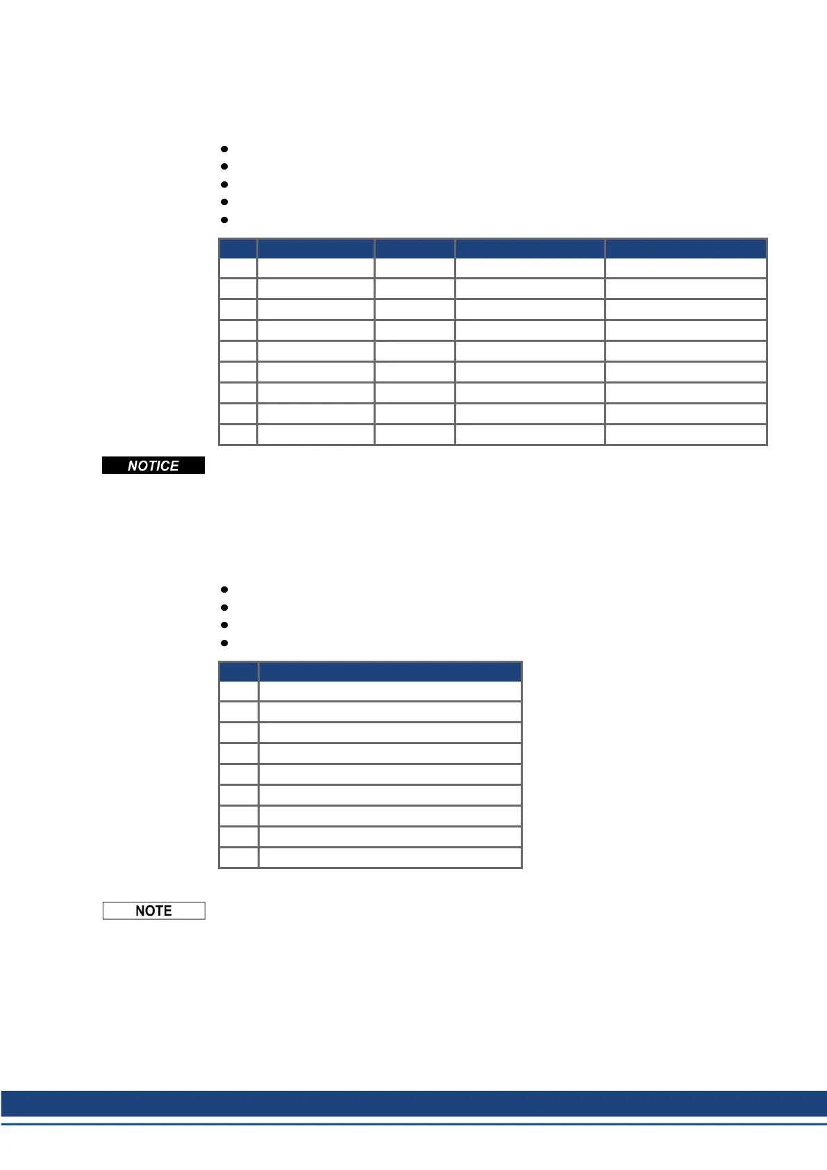
Pin Pulse/Direction CW/CCW Incremental Encoder Encoder with EnDat 2.2
1 Pulse+ CW+ A+ CLOCK+
2 Pulse- CW- A- CLOCK-
3 GND GND GND GND
4 Direction+ CCW+ B+ DATA+
5 Direction- CCW- B- DATA-
6 Shield Shield Shield Shield
7 - - Zero+ -
8 - - Zero- -
9 - - + 5 V (supply, output) +5V (supply, output)
Maximum cable length of an external incremental encoder using X9 is dependant on cable
voltage drop and external encoder power requirements. See the calculation example in the
WorkBench Online Help chapter "Electronic Gearing".
9.13.1.3 Connector X9 Output
Technical characteristics
Electrical Interface: RS-485
Max signal (channel) output frequency: 3 MHz
The pulses per revolution value are settable
Pulse phase shift: 90°±20°
Pin Emulated Encoder Output
1 Channel A+
2 Channel A-
3 GND
4 Channel B+
5 Channel B-
6 Shield
7 Channel Zero+
8 Channel Zero-
9 -
The maximum permissible cable length is 100 meters.
AKD Installation | 9 Electrical Installation
Kollmorgen | kdn.kollmorgen.com | October 2017 139

 Loading...


