AKD Installation | 7 Technical description and data
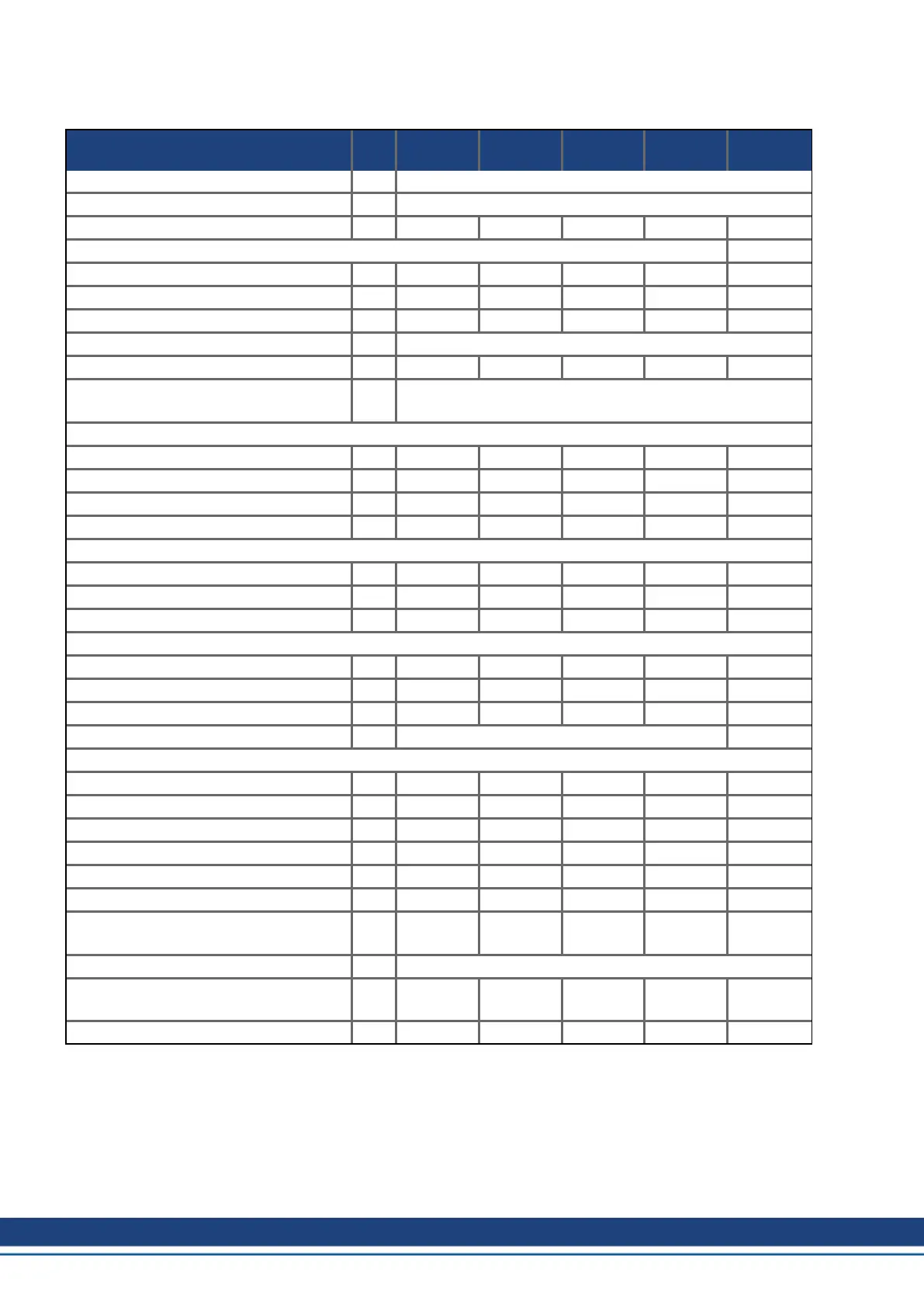
7.6 Electrical Data AKD-xzzz07
Electrical data Units
AKD-
x00307
AKD-
x00607
AKD-
x01207
AKD-
x02407
AKD-
x04807
Rated supply voltage (L1/L2/L3) V 3 x 240 V to 480 V ±10%
Rated supply input frequency Hz AC with 50 Hz to 400 Hz ±5% or DC
Rated input power for S1 operation kVA 2.24 4.49 7.65 15.2 40.9
Rated input current
at 3x240 V A 2.7 5.4 9.2 18.3 49.3
at 3x400 V A 2.7 5.4 9.2 18.3 49.3
at 3x480 V A 2.7 5.4 9.2 18.3 49.3
Permitted switch on/off frequency, mains 1/h 30
Max. inrush current (@480V, 20°C) A 9 9 9 9 9
Rated DC bus link voltage
(Bus Turn on Delay 3ph 1 sec)
V= 340 to 680
Continuous output current (± 3%)
at 240 V Arms 3 6 12 24 48
at 400 V Arms 3 6 12 24 48
at 480 V Arms 3 6 12 24 48
Peak output current (for 5 s, ± 3%) Arms 9 18 30 48 96
Continuous output power @ rated input current
at 3x240 V kVA 0.6 1.25 2.5 5 10
at 3x400 V kVA 1 2 4.2 8.3 16.6
at 3x480 V kVA 1.2 2.5 5 10 20
Peak output power (for 1 s)
at 3x240 V kVA 1.8 3.75 6.25 10 20
at 3x400 V kVA 3 6.75 10.4 16.7 33
at 3x480 V kVA 3.6 7.5 12.5 20 40
Technical data for regen circuit — (➜ # 43)
Motor inductance min.
at 240 V mH 3.2 1.6 1.3 0.6 0.3
at 400 V mH 5.3 2.6 2.1 1 0.5
at 480 V mH 6.3 3.2 2.5 1.2 0.6
Motor inductance max. mH 600 300 250 120 60
Thermal dissipation, output stage disable W max. 20 max. 20 max. 20 max. 25 max. 25
Thermal dissipation at rated current W 102 129 153 237 640
Noise emission (low speed/high speed
fan)
dB(A) 34/43 34/43 44/52 48/58 48/72
Aux. voltage supply (PELV) V= 24 V (±10%, check voltage drop)
-current B, P, T types without/with motor
brake
A= 1 / 2.5 1 / 2.5 1 / 2.5 2 / 4 2 / *
-current M type without/with motor brake A= 1.3 / 2.8 1.3 / 2.8 1.3 / 2.8 2.3 / 4.3 2.3 / *
* = motor holding brake is supplied with separated 24 V ±10% auxiliary voltage (➜ # 118).
38 Kollmorgen | kdn.kollmorgen.com | October 2017

 Loading...


