AKD Installation | 9 Electrical Installation
9.14 I/O Connection
9.14.1 Overview
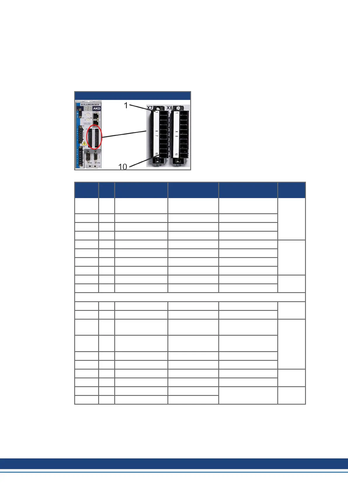
9.14.1.1 I/O connectors X7 and X8 (all AKD variants)
Standard digital and analog I/O signals are connected to X7 and X8.
AKD-B , -P, -T
Conn. Pin Signal Abbreviation Function Wiring
Diagram
X7 1 Digital Common X7 DCOM7 Common line for
X7 pins 2, 3, 4, 9, 10
(➜ #
152)
X7 2 Digital Input 7 DIGITAL-IN 7 Programmable
X7 3 Digital Input 4 DIGITAL-IN 4 Programmable
X7 4 Digital Input 3 DIGITAL-IN 3 Programmable
X7 5 Digital Output 2- DIGITAL-OUT2- Programmable (➜ # 159)
X7 6 Digital Output 2+ DIGITAL-OUT2+ Programmable
X7 7 Digital Output 1- DIGITAL-OUT1- Programmable
X7 8 Digital Output 1+ DIGITAL-OUT1+ Programmable
X7 9 Digital Input 2 DIGITAL-IN 2 Programmable,fast (➜ #
152)
X7 10 Digital Input 1 DIGITAL-IN 1 Programmable,fast
X8 1 Fault Relay Output Fault Relay Output Fault Relay Output (➜ # 160)
X8 2 Fault Relay Output Fault Relay Output Fault Relay Output
X8 3 Digital Common X8 DCOM8 Common line for
X8 pins 4, 5, 6
(➜ #
152)
X8 4 Digital Input 8 DIGITAL-IN 8 Output stage enable,
not programmable
X8 5 Digital Input 6 DIGITAL-IN 6 Programmable
X8 6 Digital Input 5 DIGITAL-IN 5 Programmable
X8 7 Analog Ground AGND Analog GND (➜ # 151)
X8 8 Analog Output + Analog-Out Actual velocity voltage
X8 9 Analog Input - Analog-In- Velocity set point (➜ # 150)
X8 10 Analog Input + Analog-In+
Digital common lines for X7 and X8 are not common to each other.
The DCOMx line should be connected to the 0V of the I/O supply when using sensors of type
"Source" with digital inputs.
The DCOMx line should be connected to the 24V of the I/O supply when using sensors of
type "Sink" with digital inputs.
146 Kollmorgen | kdn.kollmorgen.com | October 2017

 Loading...


