AKD Installation | 9 Electrical Installation
9.13 Electronic gearing, Master-slave operation (X9, X7)
It is possible to set up master/slave systems, use an external encoder as a command
encoder, secondary feedback device (dual loop control) or connect the amplifier to a third
party step controller. Depending on the signal voltage level connector X9 (5 V TTL) or X7 (24
V) must be used.
The WorkBench setup software is used for configuration. See the “Feedback 2” screen in
WorkBench for setup. FB2.SOURCE, FB2.MODE, FB2.ENCRES and others are used for
setting up an application with these interfaces.
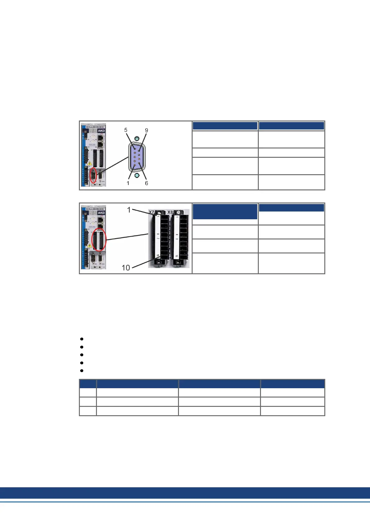
Connector X9 can be configured as an input or as an output for 5 V (TTL level) signals.
Input modes X9 Output mode
Pulse & Direction, 5 V Emulated Encoder
Output (A quad B), 5 V
CW/CCW, 5 V
Incremental Encoder
(A quad B), 5 V
Encoder with EnDat 2.2,
5 V
Connector X7, DIGITAL-IN 1/2 can be configured as an input for 24 V signals.
Input modes X7
DIGITAL-IN 1/2
Output mode
Pulse & Direction, 24 V
CW/CCW, 24 V
Incremental Encoder
(A quad B), 24 V
9.13.1 Technical characteristics and pinout
9.13.1.1 Connector X7 Input
Technical characteristics
Floating, reference common line is DCOM7
Maximum signal input frequency: 500 kHz
Sink or Source type connection possible
High: 3.5 to 30 V/2 to 15 mA , Low: -2 to +2 V/<15 mA
Update rate: firmware reads hardware input state every 250 µs
Pin Pulse/Direction CW/CCW Incremental Encoder
9 Pulse CW Channel A
10 Direction CCW Channel B
1 Common Common Common
138 Kollmorgen | kdn.kollmorgen.com | October 2017

 Loading...


