EasyManuals Logo

Kollmorgen AKD series Installation Manual

Kollmorgen AKD series
216 pages
To Next Page IconTo Next Page
To Previous Page IconTo Previous Page
Page #117 background imageLoading...
Page #117 background image
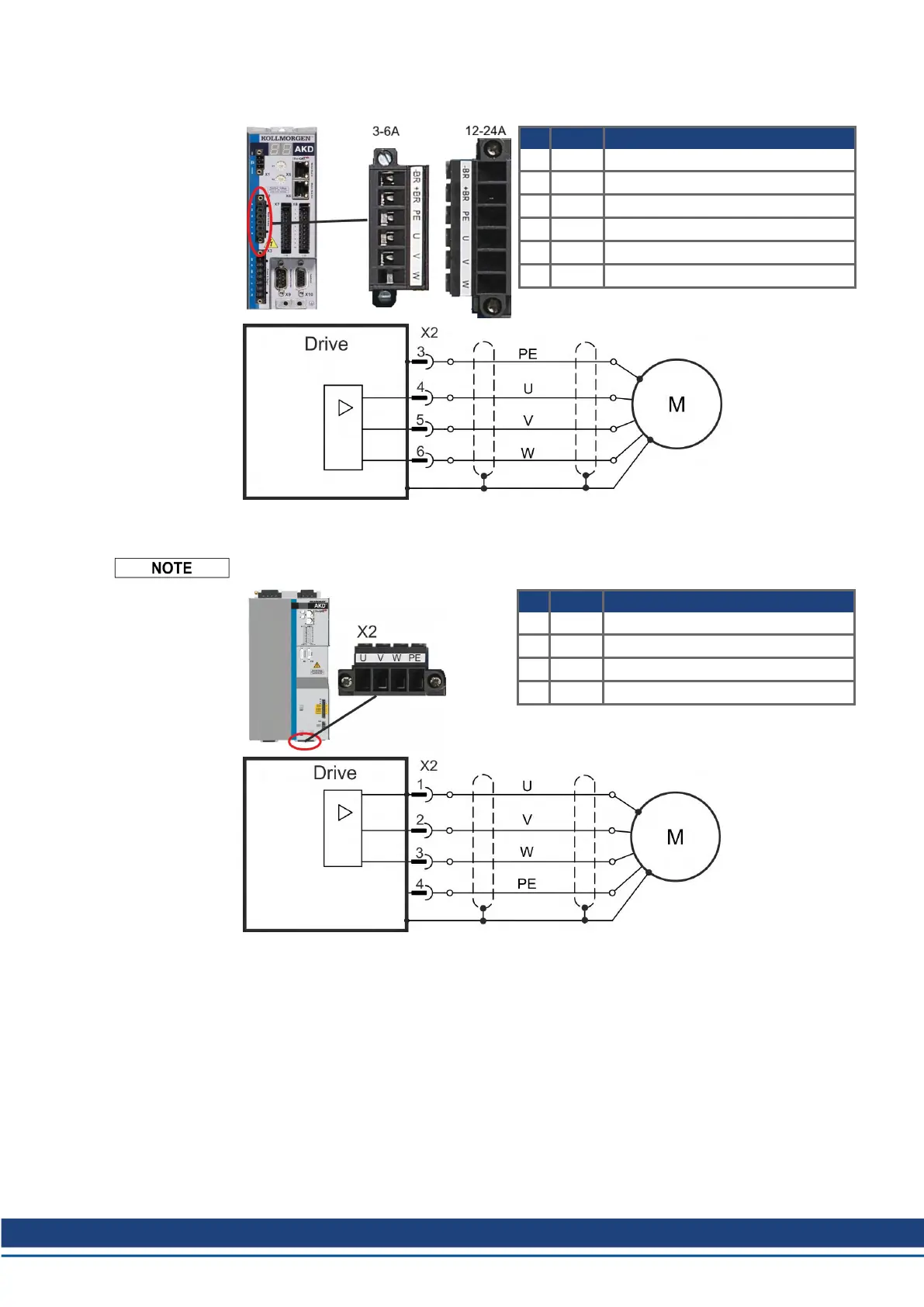
9.10.1 AKD-x003 to 024, power connector X2
Pin Signal Description
1 -BR Motor holding brake ( # 118)
2 +BR Motor holding brake ( # 118)
3 PE Protective earth (motor housing)
4 U Motor phase U
5 V Motor phase V
6 W Motor phase W
9.10.2 AKD-x048, power connector X2
Cable length maximum 25 m.
Pin Signal Description
1 U Motor phase U
2 V Motor phase V
3 W Motor phase W
4 PE Protective earth (motor housing)
AKD Installation | 9 Electrical Installation
Kollmorgen | kdn.kollmorgen.com | October 2017 117

Table of Contents

Other manuals for Kollmorgen AKD series

Questions and Answers:

Question and Answer IconNeed help?

Do you have a question about the Kollmorgen AKD series and is the answer not in the manual?

Kollmorgen AKD series Specifications

General IconGeneral
Continuous CurrentUp to 180 A
Control ModesPosition, Velocity, Torque
Communication InterfacesEtherCAT, CANopen, Modbus TCP/IP
Feedback OptionsResolver, Encoder
Safety FeaturesSafe Torque Off (STO), Safe Stop 1 (SS1)
Protection FeaturesOvervoltage, Undervoltage, Overcurrent, Short Circuit, Overtemperature
Switching Frequency8 kHz, 16 kHz
Ambient Temperature0°C to 40°C
Operating Temperature0 - 40 °C (derating may apply)
Humidity5% to 95% non-condensing

Related product manuals