AKD Installation | 9 Electrical Installation
9.11.3 Functionality
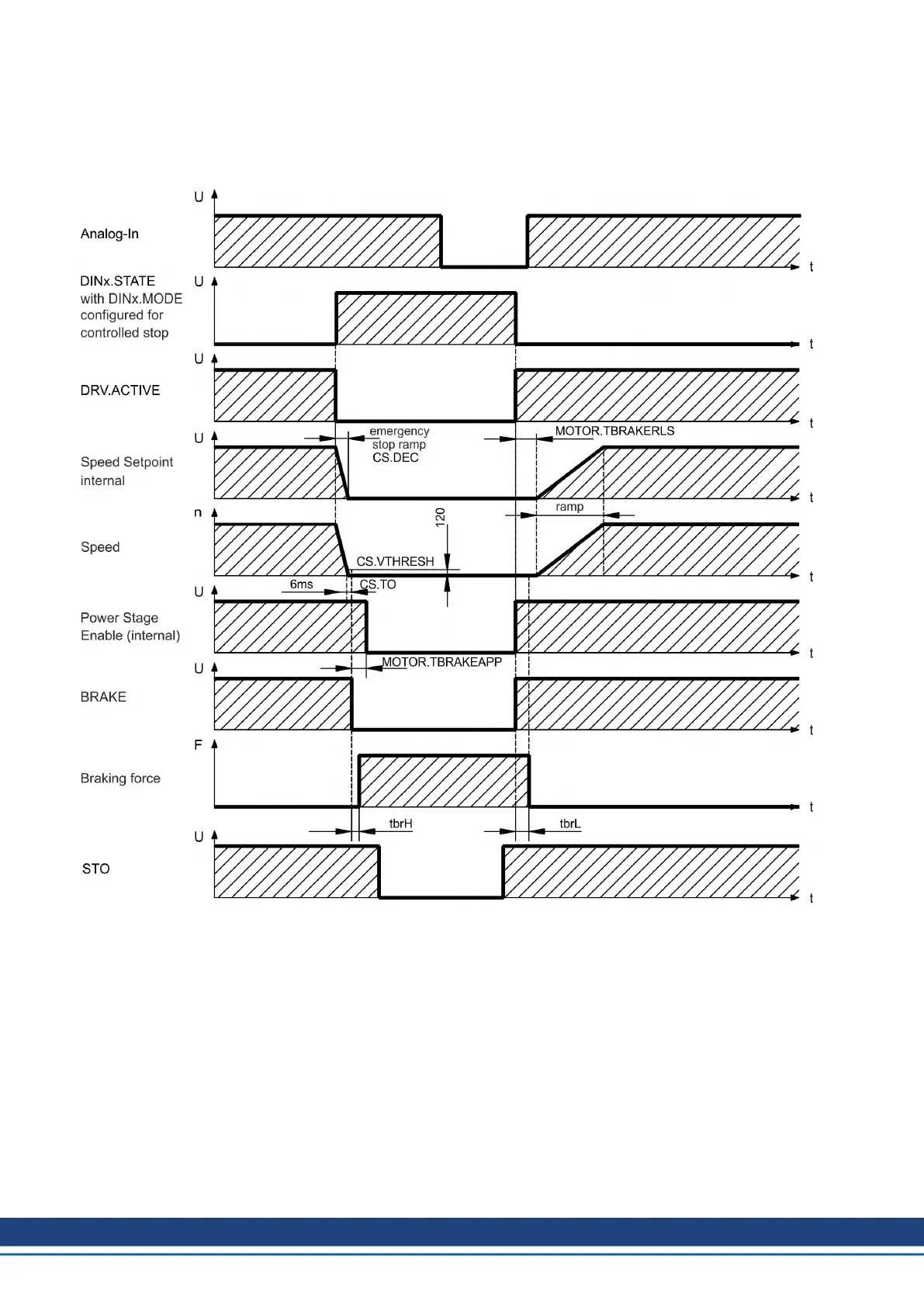
The brake function must be enabled through a parameter. The diagram below shows the tim-
ing and functional relationships between the controlled stop signal, speed,and braking force.
All values can be adjusted with parameters; values in the diagram are default values.
The speed setpoint of the drive is internally driven down an adjustable ramp (CS.DEC) to 0V.
With default values the output for the brake is switched on when the speed has reached
120rpm (CS.VTHRESH) for at least 6ms (CS.TO). The rise (t
brH
) and fall (t
brL
) times of the
holding brake that is built into the motor are different for the various types of motor.
120 Kollmorgen | kdn.kollmorgen.com | October 2017

 Loading...


