EasyManuals Logo

Kollmorgen AKD series Installation Manual

Kollmorgen AKD series
216 pages
To Next Page IconTo Next Page
To Previous Page IconTo Previous Page
Page #137 background imageLoading...
Page #137 background image
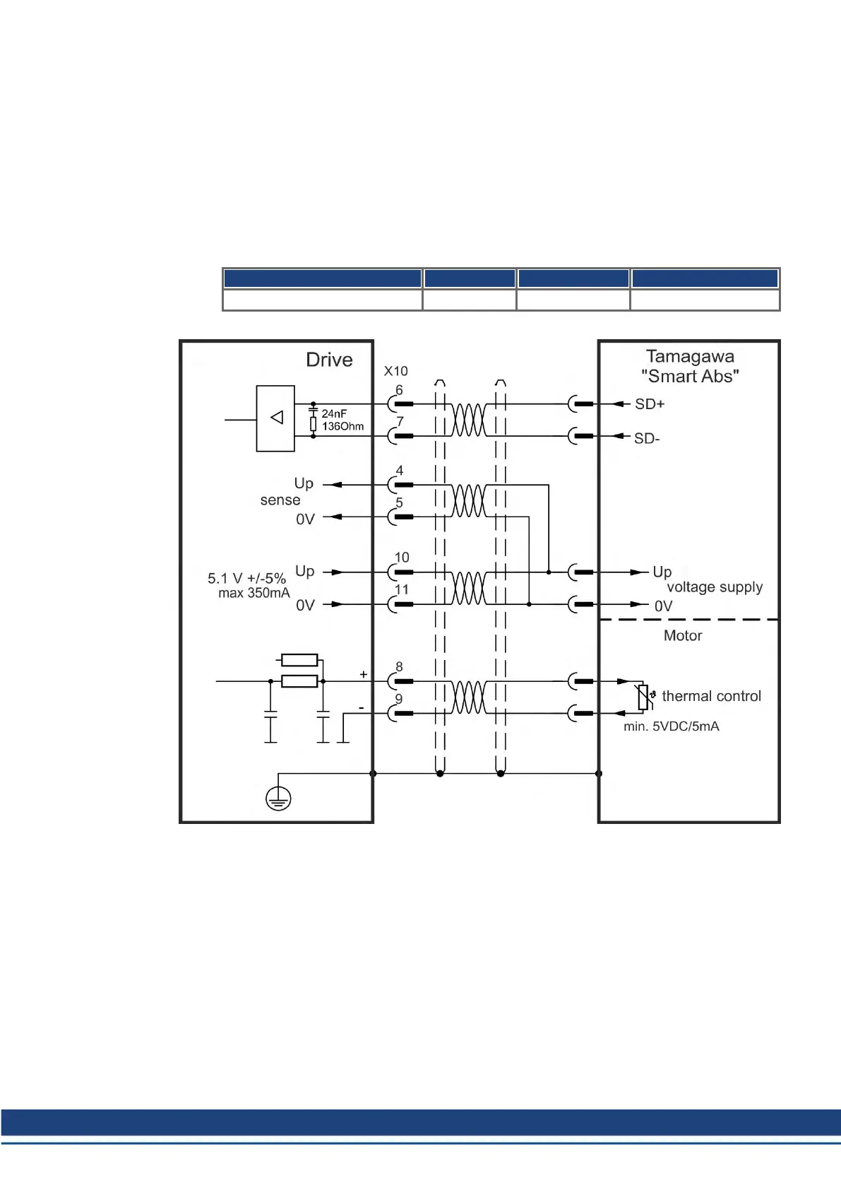
9.12.15 Tamagawa Smart Abs Encoder
The diagram below shows the wiring of Tamagawa "Smart Abs" encoders (Tamagawa Seiki
Co. Ltd. S48-17/33bit-LPS-5V or similar) as a primary feedback system for AKD with "NB"
(rev 8+) control board. The thermal control in the motor is connected via the encoder cable
and evaluated in the drive. If no thermal control is in the motor, the cable must short pins 8
and 9. The "Sense" signal is optional, and can be omitted if the encoder cable is short and no
significant voltage drop is on the cable. The voltage drop depends on the cable length and
gage and the encoder current consumption.
If cable lengths of more than 25 m are planned, please consult customer support.
Type FBTYPE Up Frequency Limit
S48-17/33bit-LPS-5V 42 5.1 V +/-5% 2.5 MHz
AKD Installation | 9 Electrical Installation
Kollmorgen | kdn.kollmorgen.com | October 2017 137

Table of Contents

Other manuals for Kollmorgen AKD series

Questions and Answers:

Question and Answer IconNeed help?

Do you have a question about the Kollmorgen AKD series and is the answer not in the manual?

Kollmorgen AKD series Specifications

General IconGeneral
Continuous CurrentUp to 180 A
Control ModesPosition, Velocity, Torque
Communication InterfacesEtherCAT, CANopen, Modbus TCP/IP
Feedback OptionsResolver, Encoder
Safety FeaturesSafe Torque Off (STO), Safe Stop 1 (SS1)
Protection FeaturesOvervoltage, Undervoltage, Overcurrent, Short Circuit, Overtemperature
Switching Frequency8 kHz, 16 kHz
Ambient Temperature0°C to 40°C
Operating Temperature0 - 40 °C (derating may apply)
Humidity5% to 95% non-condensing

Related product manuals