AKD Installation | 9 Electrical Installation
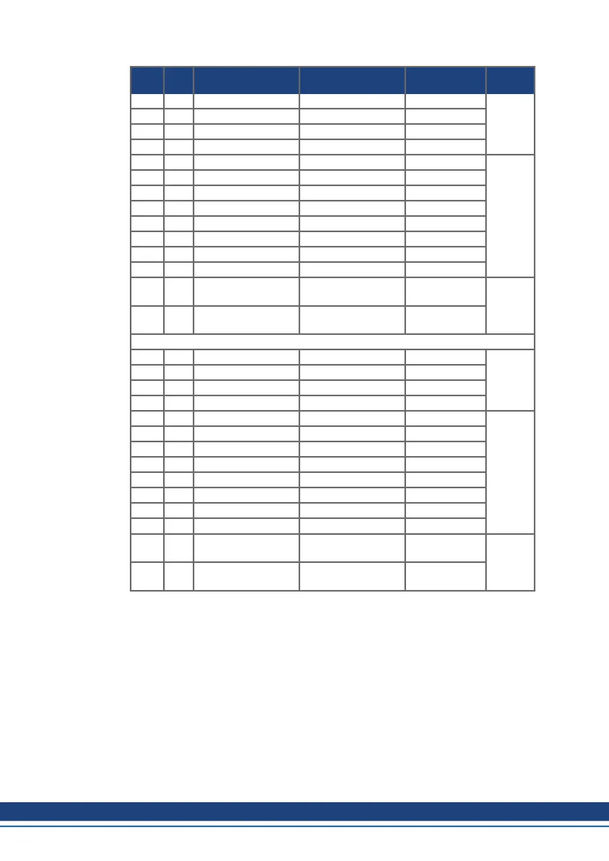
Conn. Pin Signal Abbreviation Function Wiring
Diagram
X23 1 Analog Output 2 + Analog-Out2 Programmable (➜ # 151)
X23 2 reserved n.c. n.c.
X23 3 Analog Ground AGND Programmable
X23 4 reserved n.c. n.c.
X23 5 Digital Output 21+ DIGITAL-OUT 21+ Programmable (➜ # 161)
X23 6 Digital Output 21- DIGITAL-OUT 21- Programmable
X23 7 Digital Output 22+ DIGITAL-OUT 22+ Programmable
X23 8 Digital Output 22- DIGITAL-OUT 22- Programmable
X23 9 Digital Output 23+ DIGITAL-OUT 23+ Programmable
X23 10 Digital Output 23- DIGITAL-OUT 23- Programmable
X23 11 Digital Output 24+ DIGITAL-OUT 24+ Programmable
X23 12 Digital Output 24- DIGITAL-OUT 24- Programmable
X23 13 Relay Output 25 DIGITAL-OUT 25 Programmable,
relay
(➜ # 163)
X23 14 Relay Output 25 DIGITAL-OUT 25 Programmable,
relay
X24 1 Analog Input 2+ Analog-In2+ Programmable (➜ # 150)
X24 2 Analog Input 2- Analog-In2- Programmable
X24 3 Analog Ground AGND Programmable
X24 4 reserved n.c. n.c.
X24 5 Digital Output 26+ DIGITAL-OUT 26+ Programmable (➜ # 161)
X24 6 Digital Output 26- DIGITAL-OUT 26- Programmable
X24 7 Digital Output 27+ DIGITAL-OUT 27+ Programmable
X24 8 Digital Output 27- DIGITAL-OUT 27- Programmable
X24 9 Digital Output 28+ DIGITAL-OUT 28+ Programmable
X24 10 Digital Output 28- DIGITAL-OUT 28- Programmable
X24 11 Digital Output 29+ DIGITAL-OUT 29+ Programmable
X24 12 Digital Output 29- DIGITAL-OUT 29- Programmable
X24 13 Relay Output 30 DIGITAL-OUT 30 Programmable,
relay
(➜ # 163)
X24 14 Relay Output 30 DIGITAL-OUT 30 Programmable,
relay
148 Kollmorgen | kdn.kollmorgen.com | October 2017

 Loading...


